PRI Board
Board Description
The PRI board contains one or two (depends on the part number) ISDN interfaces and PCM bus timing circuits. PRI 1 is designed as an internal interface (with an activated LCR function) and PRI 2 as an external interface (all calls from the port are always routed to PRI 1). The interface can work in the MASTER or SLAVE mode (set the PRI 1 mode using the web interface and PRI 2 has always the opposite mode). The output can be configured as TERMINAL (TE) or NETWORK (NT) by jumpers (switching of wires – for software switch you have to use the web interface!). The settings of these jumpers HAVE TO match the PRI configuration – two NT and TE modes will cause malfunction of the PRI board or back-up connection* ! The board is designed on a 4-layer PCB of the size of 160x100mm. There are also 5 (or 8 in 2ISDN PRI) board status indicators, which are located on the front panel.
- The PRI board contains four switches (can be deactivated by jumpers), which provide hardware connection between PRI 1 and PRI 2 in case the system is switched off or inoperative.
|
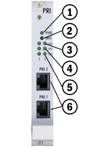
- Board supply indication
- Shining: Switched on
- Flashing: Board in the sleep mode
- Board initialisation or error state
- Shining (up to 1 minute): Firmware upgrading
- Continuous shining or flashing: Board initialisation failure
- Status of ISDN layer 3 on PRI 1/2 interfaces
- Shining: One or more calls are connected over selected interface
- Flashing: B-channel in restartLight off: No active call
- Status of ISDN layer 2 on PRI 1 (2) interfaces:
- Shining: Layer 2 successfully established
- Flashing: Layer 2 in the establishing process
- Light off: Layer 2 disconnected
- Status of ISDN layer 1 on PRI 1 (2) interfaces:
- Shining: Layer 1 successfully established
- Flashing: Layer 1 in the establishing process
- Light off: Layer 1 disconnected
- Physical RJ-45 connectors for ISDN PRI 1 and PRI 2 interfaces. Before you plug in your ISDN connection please check whether the wiring configuration matches the ISDN connection requirements!
Tip
- The LED statuses provide basic information on the ISDN interface only. For details on the ISDN interface state refer to the web interface.
Configuration Jumpers
|
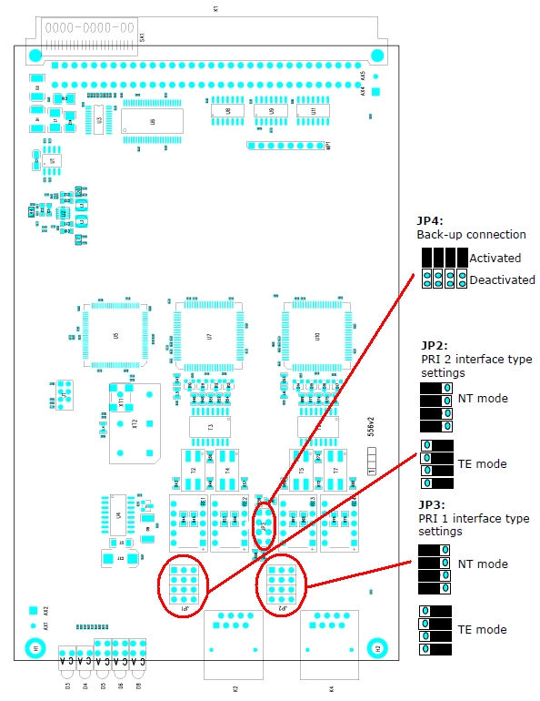
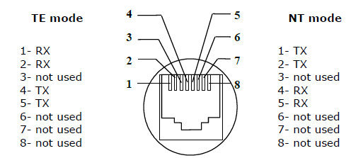
There are three configuration jumper blocks on the PRI board. JP2 and JP3 are used for hardware switching of the ISDN PRI connector into the TE/NT configuration. This operation means only swapping of the transmitting and receiving connector pairs, the interface configuration must be made using the web interface. With jumper JP4 you can activate/deactivate the back-up connection between PRI 1 and PRI 2 in case the system is switched off or the PRI board is not handled by system.
Warning
- The back-up connection (JP4) works only in case the wire settings of PRI 1 (JP3) and PRI 2 (JP2) are set in the opposite way (e.g. PRI 1 as NT, PRI 2 as TE).
Note
- Boards with just one PRI interface (1PRI boards) have the same settings as the PRI 1 interface on 2PRI boards. And there is no back-up connection (JP4) either.
Positions of Tx and Rx Wires
|
Example of Connection with 1ISDN PRI Board
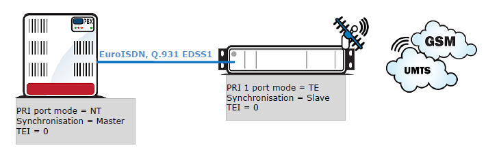
Example of Connection with 2ISDN PRI Board
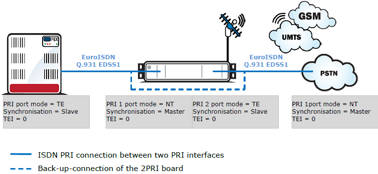
Warning
- The ISDN port mode (TE or NT) and synchronisation type (Master/Slave) must be different on the PBX (PSTN) and on the gateway. The TEI number must have the same value (default = 0).