3.4 2N® External Routing Machine
Installation
CD Image
An automatic installation CD (part No. 507424E) has been created for installation purposes. This installation CD automatically prepares the system and installs the requested application.
Minimum PC Hardware Requirements
- Procesor: Intel P4, 2.4GHz or higher
- RAM: 2048 MB RAM
- HDD: 60GB SATA
- CD-ROM: Only CD-R
- LAN: Ethernet 100BaseT
Note
- The ERM web interface is available in versions ERM v4 and higher!
Installation Procedure
Caution
- By using the installation CD you remove ALL data from the hard drive!
This installation is automatic and requires a very low user interaction.
Follow the instructions below to install a perfectly working system.
Set your PC to use the CD ROM as the default boot device.
Place the installation CD into the CD ROM.
After starting your PC, you will get the following screen. You can choose any of the available booting options. Automatic installation is the first option and will start in 3 seconds.
|

|
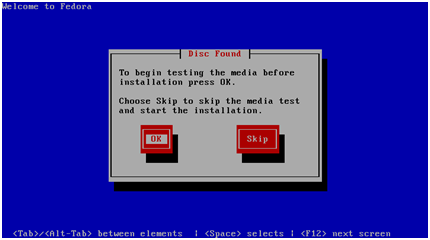
You can test the installation CD before installation. Choose OK to test the CD or Skip to continue the installation process.
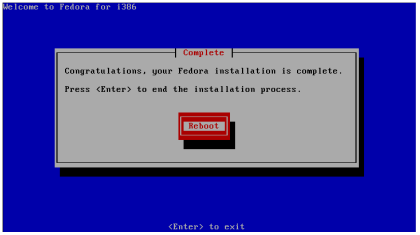
The installer will automatically format the hard drive and install all system files. When the installation is finished, the installer will wait for reboot confirmation. Press ENTER to continue.
Remove the CD from the CD ROM and let the new system boot.
|
To finish the system settings log in as the Admin user with the 2n password.
The wizard will help you set the network and install the package correctly.
Network Settings
You can set the network during the first login. A graphical wizard will help you set the IP address, network mask and default gateway. Use TAB to move between options. Use SPACE to select or unselect options. You can also change the IP by running the command set-up.
Time Zone and Time Synchronisation
Because the routing rules are based on time and date, be sure to set the correct time zone and synchronise time. For time synchronisation use the NTP protocol and so you need the Internet connection.
Package Installation
Choose the package to be installed. You can choose either the 2N® ERM or 2N® SIM Star Server application.
Configuration via WEB interface
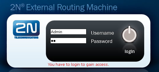
Enter http://IP_address_PC/erm into your browser address row to access the ERM web interface.
Caution
- The manufacturer supplies the gateways with a predefined default user account Admin with default password 2n . Mind the Upper/Lower Case while entering the user name and password! The first thing you should do for safety reasons after putting your gateway in operation is to change the administrator password.
|
Gateway Connection
Access the ERM configuration via the web interface sections. Use this interface to fully configure the ERM and manage the database table records.
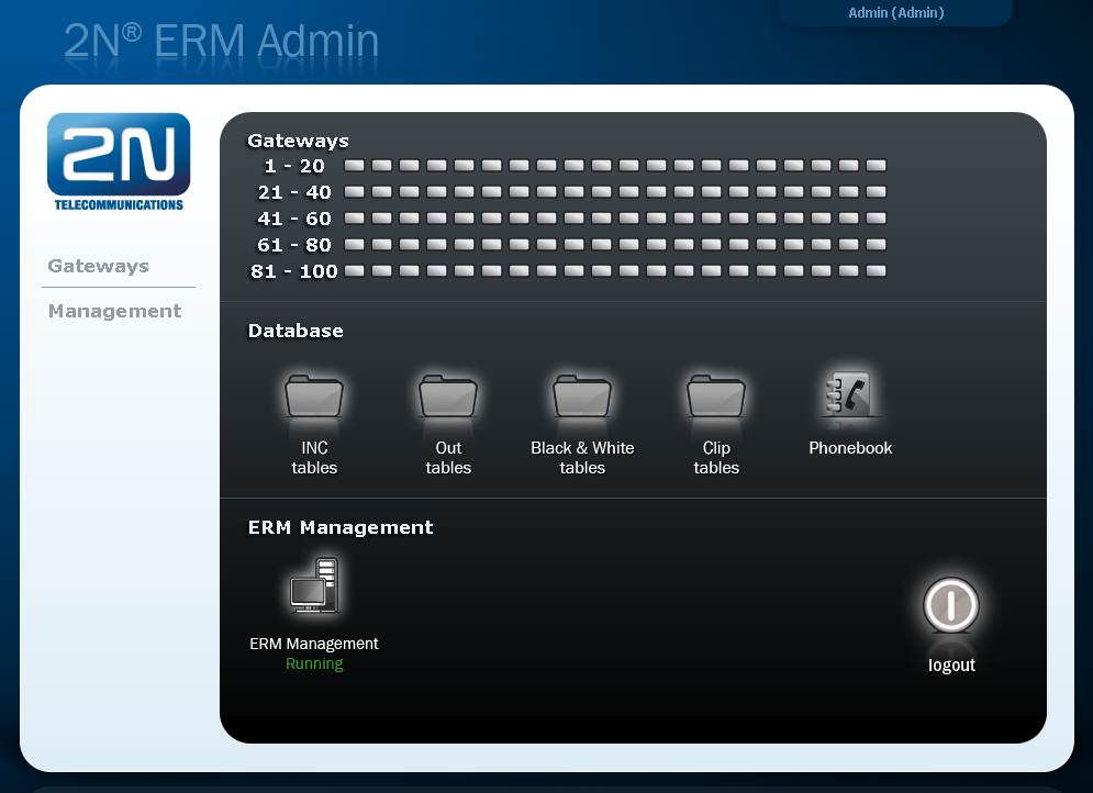
The configuration consists of the following sections:
- Gateways – section for information related to the gateway, the maximum number of connected gateways is 100.
- Database – for manage all database tables concerting ERM.
- INC tables – routing of incoming calls from GSM/UMTS
- Out tables – routing of outgoing calls according Calling party number (CLIP)
- Black & White tables – outgoing calls routing according to Black & White CDN list
- Clip tables – routing of outgoing calls according to Called party number
- Phonebook – telephone directory table (for 2N® NetStar system only).
- ERM Management – section for general configuration of ERM.
- The 2N® ERM server will not become functional until the ERM licence file is uploaded.
Licence
The ERM licence is per gateway connection. The licence is generated by the 2N Technical Support and based on the gateway serial number.
Upload the current licence file via the ERM web interface (ERM Management – Licence).
Gateway Section
The Gateway section contains the following items:
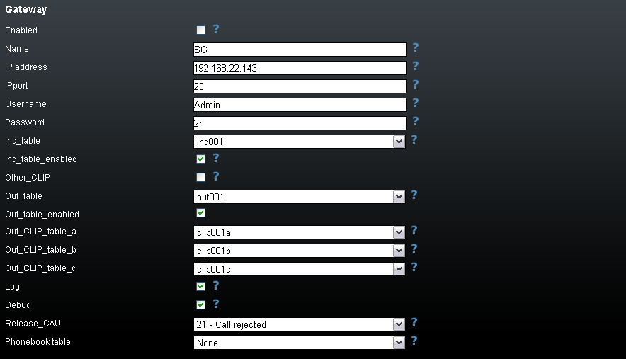
Key | Value | Description |
Enabled | 0 or 1 | Activates (1) or deactivates (0) the use of the gateway. |
IPaddress | IP address in format xxx.xxx.xxx.xxx | Remote GSM gateway IP address. Set this connection for ERM remote control. |
IPport | IP port number | Remote gateway communication port (default=23). |
Username | String | Username for gateway access through the Telnet protocol (default=2n). |
Password | String | Password for gateway access through the Telnet protocol (default=2n). |
Inc_table | inc001 to inc100 | Name of the table that includes record for incoming GSM call filtering. One table may be shared by multiple GSM gateways. |
Inc_table_enabled | True or False | Enables (True) or disables (False) filtering of incoming calls. |
Other_CLIP | 0 or 1 | Determines whether an identified GSM CLIP shall be rejected (0) or received (1). |
Out_table | out001 to out100 | Name of the table used for outgoing call routing. One table may be shared by multiple GSM gateways. |
Out_CLIP_table | clip001 to clip100 | Name of the table used for outgoing call routing. One table may be shared by multiple GSM gateways. |
Out_table _enabled | True or False | Enables (True) or disables (False) the use of the Out_table. |
Log | 0 or 1 | Activates (1) or deactivates (0) LOG generation. |
Debug | 0 or 1 | Activates (1) or deactivates (0) debug generation. |
Release_CAU | Number 1-255 | ISDN releases CAU which is sent if a call is rejected (default=21). |
| Phonebook table | phonebook001-phonebook100 | Name of the telephone directory table (for the 2N® NetStar system only). |
Inc Table
This table is used for filtering incoming calls from GSM networks.
|
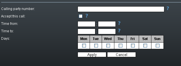
- CLIP – enter the strings to be directly compared with the CLIP received.
- Restriction – enter the value to be assigned to each CLIP determining whether the incoming call with the CLIP shall be rejected (O) or received (1).
- Time from – set the beginning value of the time interval (hh:mm) for the selected rule.
- Time to – set the end value of the time interval (hh:mm) for the selected rule.
- Day – define a day in the week on which the rule shall be applied (1= Monday, …, 7 = Sunday).
Incoming table structure:
CLIP | Restriction | Time from | Time to | Day |
+420605234354 | 1 | 00:00 | 12:00 | 1234567 |
+420775234091 | 0 | 12:00 | 24:00 | 1234567 |
Out Table
This table is used for identification of the subgroup from which the call is coming. The search result is used for search in the clip_table.
|
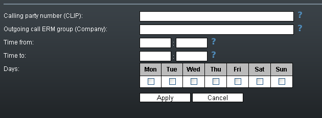
- CGP – enter the strings to be directly compared with the CLIP received. The '_' character is used as a masking character for one numeric character.
- Company – set the value to be assigned to each CGP determining to which subgroup the CGP is assigned. If there is no match, the received CGP is assigned to subgroup 0.
- Time from – set the beginning value of the time interval (hh:mm) for the selected rule.
- Time to – set the end value of the time interval (hh:mm) for the selected rule.
- Day – define a day in the week on which the rule shall be applied (1= Monday, …, 7 = Sunday).
Out table structure:
CGP | Company | Time from | Time to | Day |
261301___ | 1 | 00:00 | 12:00 | 1234567 |
2353215__ | 2 | 12:00 | 24:00 | 1234567 |
261333111 | 100 | 00:00 | 24:00 | 1234567 |
261333222 | 101 | 00:00 | 24:00 | 12345 |
Clip Tables
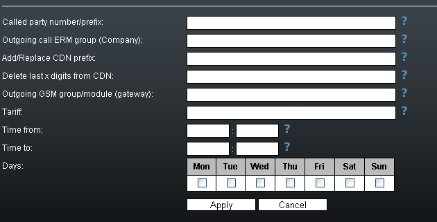
- Prefix – define the received called number or a part of it (the number is checked from the left).
- Company – use this parameter to define to which subgroup the rule is to be applied.
- Change prefix – use this parameter to modify the number to be dialled. The '-' character removes one character from the left side of the called number. The other characters are added to the called number beginning.
- Delete last – use this parameter to remove characters from the right-hand side of the called number. The value defines how many characters should be removed.
- Out group – use this parameter to specify the outgoing group for call routing. If the group is set to 0, the call will be rejected. For direct routing to a selected GSM module, use G##, where ## is the GSM module number.
- Tariff – use this parameter to specify the Tariff number.
- Time from – set the beginning value of the time interval (hh:mm) for the selected rule.
- Time to – set the end value of the time interval (hh:mm) for the selected rule.
- Day – define a day in the week on which the rule shall be applied (1 = Monday, …, 7 = Sunday).
Clip table structure:
Prefix | Company | Change prefix | Delete last | Out group | Time from | Time to | Day |
605205697% | 1 | 0 | 129 | 00:00 | 12:00 | 1234567 | |
605205697#% | 4 | 1 | 9 | 12:00 | 24:00 | 1234567 | |
605% | 1 | #31# | 0 | 129 | 00:00 | 24:00 | 1234567 |
605% | 2 | +420 | 0 | 349 | 00:00 | 24:00 | 1234567 |
0605% | 3 | -#31# | 0 | 59 | 00:00 | 24:00 | 1234567 |
608% | 1 | #31#+420 | 0 | 0 | 00:00 | 24:00 | 1234567 |
% | 1 | 0 | 9 | 00:00 | 24:00 | 1234567 | |
% | 100 | 0 | G10 | 00:00 | 24:00 | 1234567 | |
% | 101 | 0 | G1 | 00:00 | 12:00 | 1234567 | |
% | 101 | 0 | G12 | 12:00 | 24:00 | 1234567 |
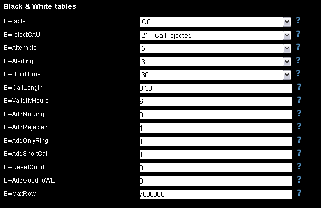
Black & White Tables
Set the rules to disable routing for calls that failed to meet the set parameters before, such as unconnected calls, short calls, rejected calls, and so on.
| Black & White tables | ||
|---|---|---|
| Bwtable | BW001-BW100 | Name of the B&W table. |
| BwrejectCAU | Number 1-255 | ISDN releases CAU to be sent if a call is rejected (default=21). |
| BwAttempts | 1 – 50 | Number of attempts before the record change to restricted. |
| BwAlerting | 0 – 30 | Minimum length of the Outgoing call alerting state. |
| BwBuildTime | 0 – 45 | Maximum length of Call building. |
| BwCallLength | mm:ss | Minimum length of the active call. |
| BwValidityHours | 0, 1-999 | Validity time of a record in the database. If you set 0 there is no time limit for records. |
| BwAddNoRing | 0, 1 | Call with no ringing state will be marked as "faulty". |
| BwAddRejected | 0, 1 | Rejected call will be marked as "faulty". |
| BwAddOnlyRing | 0, 1 | Call with ringing state and no active state will be marked as "faulty". |
| BwAddShortCall | 0, 1 | Short call will be marked as "faulty". |
| BwResetGood | 0, 1 | One outgoing call that is not marked as "faulty" will restore BWAttepmts counter back to "0". |
| BwAddGoodToWL | 0,1 | One outgoing call that is not marked as "faulty" will be automatically added to the whitelist. |
| BwMaxRow | 0, 20000–7000000 | Maximum number of records in the selected database table. |
The BW table records can have three different states.
- 0 – White list – the record is enabled.
- 1 – Counting – the record is in the state of counting. When the threshold value is reached, a change in the Black List will occur.
- 2 – Black list – the record is disabled.
B&W table structure:
| Called party number | Length of Alerting state | Buildtime | Length of connected call | Release cause | Number of "wrong“ calls | TimeStamp | State of record |
|---|---|---|---|---|---|---|---|
| 601123456 | 15 | 10 | 00:33:00 | 1 | 3 | 2012-10-22 13:21:05 | 1 |
Note
- The maximum count of Black & White table records is 7000000.
ERM Management
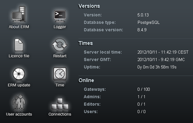
Versions
This section provides information on the firmware versions.
- Version – gives information on the firmware version.
- Build – gives information on the firmware build version.
- Database type – gives information on the database type.
Times
This section provides information on the 2N® ERM Server times.
- Server local time – gives the 2N® ERM Server local time derived from the time zone defined.
- Server GMT – gives the 2N® ERM Server time without time shift. GMT stands for the Greenwich Mean Time and is taken over directly from the BIOS.
- Uptime – gives the time from the last OS power up.
Online
This section provides information on the count of currently connected gateways and users.
About ERM
The menu provides essential contact information on the 2N TELEKOMUNIKACE a.s. company. You will find here the address, telephone and fax numbers and e-mail address of the Sales Department and Technical Support as well as a link to the 2N web sites.
Logger
The menu provides view LOG records in 2N® ERM Server. The records are marked with a timestamp.
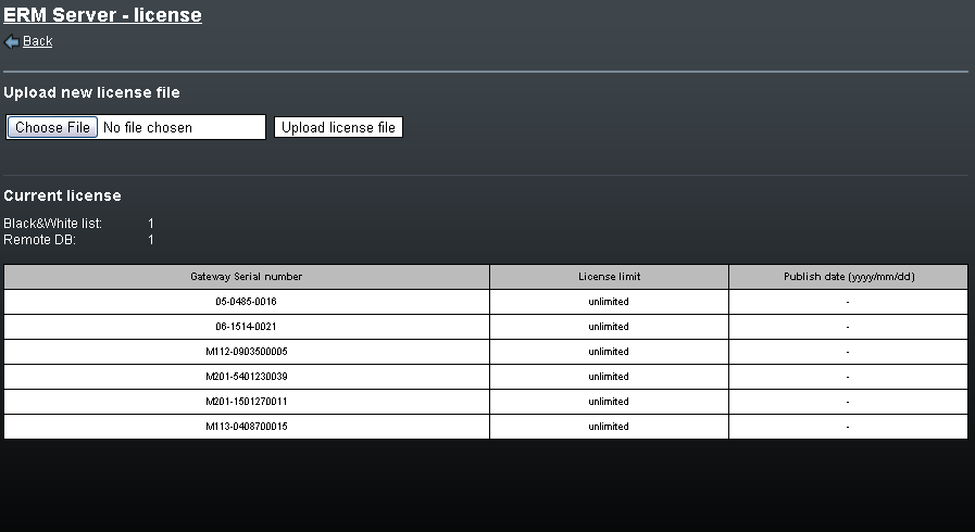
Licence File
Some 2N® ERM Server functions and GSM gateway connections are subject to licences. To manage the licences use this menu.
- Current licence limitations – check whether your current licence includes the following two system functions. These functions are subject to licence:
- Black&White list
- Remote DB
- Licensed gateways – displays a list of serial numbers of all the GSM gateways that may be used with 2N® ERM Server. 2N® ERM Server cannot be connected to gateway types other than those listed here. Every record also includes information on the licence expiry.
- Upload new licence file – helps you upload a new licence file. Select the file location using the Browse button and push Upload licence file.
Restart
- Restart ERM Server – use this option to restart 2N® ERM Server.
- Load default configuration and restart ERM Server – use this option to load default canfiguration and restart 2N® ERM Server.
- Load default database configuration – use this option to load default canfiguration 2N® ERM Server.
ERM Update
This section helps you update your 2N® ERM Server. Select the file location using the Browse button and push Upload update file.
Time
This section helps you set the 2N® ERM Server time.
User Accounts
This section helps you add/remove/edit the user accounts. The following two accounts are available in the default setting.
| Username | Password | Privileges |
|---|---|---|
| 2n | 2n | Editor |
| Admin | 2n | Admin |
Connections
This section helps you monitor the connected users.
ERM Control
The erm user is used for administration purposes. To log in as the erm user use the ermserver password. The ERM is controlled and administered by the erm utility. To launch this utility use the following syntax (the statement values are not case sensitive):
erm statement parameters
| Statement | Action |
start | Launches the ermserver service. If the service is running, it writes out a report and terminates operation. |
stop | Terminates the ermserver service. Unfinished requests, if any, are completed. |
restart | Restarts the ermserver service. |
Status | Writes out the ermserver service status, i.e. whether or not it is running. |
import <db_name> <CSV_file> <replace_duplicates> | Imports a new record into database table: <db_name> - name of the database table to be used for import. <CSV_file> - name of the CSV file to be used for import. If the file is unavailable in the current directory, the full path has to be listed. The CSV file values are separated with a comma (0x2C). The structure of all related tables is described in the ERM database structure section. <replace_duplicates> - sets whether duplicate lines should be replaced (True) or kept (False). Example of usage: erm import clip001 clip001.csv true |
export <db_name> <CSV_file> | Exports the database table to the CSV file.Example of usage: erm export clip001 clip001_backup.csv |
Erase <db_name> | Deletes the content of a selected database table.Example of use: erm erase clip001 |
Copy <source_db_name> <dest_db_name> | Copies the database table: <source_db_name> - name of the source table; <dest_db_name> - name of the destination table.Example of usage: erm copy clip001 clip002 |
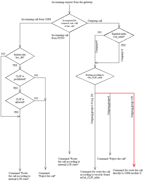
Description of ERM Function
After start, the ERM is connected automatically to the defined GSM gateways, activating the external call routing process in them. During this process, the GSM gateway automatically sends information on any new call to the ERM and awaits reply with call instructions within 2 seconds. If no reply comes from the ERM within this timeout, the call is routed according to the internal routing tables.
Note
- You can increase the timeout to up to 6 seconds if the gateway - server communication is too slow.
The functional diagram below shows the request processing procedure: