Wiegand module - How to setup Wiegand together with the Access Unit?
The Wiegand module (Part No. 9155037) is one of the 2N IP intercom modules and is used for connecting an external Wiegand device (RFID card reader, fingerprint or other biometric data reader) and/or connecting the 2N IP intercom products system to an external security exchange. All the inputs and outputs are galvanically isolated from the 2N® system with insulation strength of 500 V DC. Wiegand can be used together with the 2N IP intercoms or together with the 2N® Access Unit.
Info
- You don't need any license to be able to use Wiegand module.
- This scenario is not possible with 2N Access Unit M, as it is not possible to connect any additional module to this unit.
Wiegand module overview
- The module contains two 2N® IP Verso bus connectors.
- These two connectors are fully interchangeable and can be used both as inputs from the main unit and outputs to other modules.
- If this module is the last one on the bus, one of the connectors remains unconnected.
- The module package includes an 80 mm long interconnecting cable.
- The module name is configured in the Module name parameter in the Hardware / Extenders menu.
The input LED IN is addressed as follows: <module_name>.<input1>, e.g. module2.input1.
The input Tamper is addressed as follows: <module_name>.<tamper>, e.g. module2.tamper.
The output LED OUT (negated) is addressed as follows: <module_name>.<output1>, e.g. module2.output1.
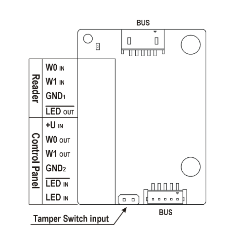
Figure 1: Wiegand interface description
| Section | Interface | Description |
|---|---|---|
| Reader | W0 IN, W1 IN, GND1 | Isolated 2-wire WIEGAND IN |
LED OUT | Isolated open LED OUT switched against GND1 on WIEGAND IN side (up to 24 V / 50 mA) | |
| Control Panel | +U IN | +UIN (5 to 15 V DC) WIEGAND OUT power supply input |
W0 OUT, W1 OUT, GND2 | Isolated 2-wire WIEGAND OUT | |
LED IN (negated) | Isolated input for open LED IN, input activated by GND2 | |
LED IN | Isolated input for open LED IN, input activated by +U | |
| G | +U IN WIEGAND OUT active supply LED indicator | |
| TAMPER | Tamper switch (Part No. 9155038) input |
Applications
There are basically two scenarios in which Wiegand module can be used:
- Forward the information towards the 3rd party access control systems or other systems that are able to use Wiegand interface and protocol.
- Accept the information from 3rd party RFID card readers or biometric data readers.
Based on the scenario it is necessary to choose the right direction of the information flow. This can be done in the section Hardware -> Extenders -> Direction.
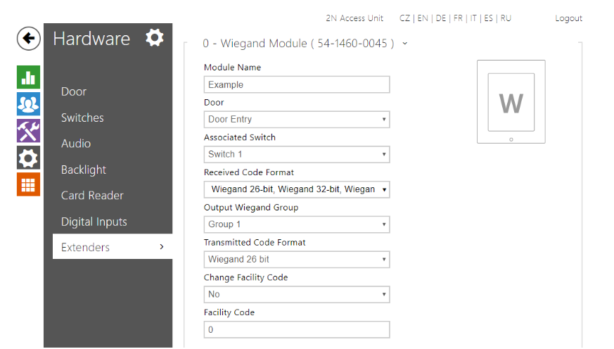
Figure 2: Wiegand parameters setup
Description of the parameters
- Module name - set the module name for input/output specification in the SetOutput, GetInput and InputChanged objects in the Automation settings.
- Direction - set the passage direction for the card reader (Not Specified, In, Out) for the attendance system purposes.
- Multiple authentication - enable multiple user authentication via a Wiegand-connected card reader (or the user authentication option defined in Directory / Users). Disable multiple authentication for a card reader to cancel code authentication via the numeric keypad.
- Associated switch - set the number of the switch to be activated whenever a valid code is received.
- Received code format - set the format for the codes to be received (Wiegand 26, 32, 37 and RAW).
- Card read signalling - set one of the card reading signalling modes: Full - acoustic signals distinguish valid/invalid cards, Single Beep - one beep signals both valid and invalid cards, None - acoustic signalling is disabled.
- Forward to Wiegand output - set the group of Wiegand outputs to which all the received codes will be resent.
- Transmitted code format - set the format for the codes to be transmitted (Wiegand 26, 32, 37 and RAW).
- Output Wiegand group - assign the output Wiegand group to which the codes from the connected card readers or Wiegand inputs can be resent.
Outgoing direction
In this scenario you are able to send the card ID from the 2N Access Unit towards the 3rd party access control system. The 3rd party system is controlling the access. Control panel interfaces are used for the connection in this scenario.
![]()
Once you are using Control panel Wiegand module interfaces, be aware that this side of the module has to be powered by the external power supply.
Incoming direction
In this scenario it is necessary to use the first section of the Wiegand module called Reader (see the Figure 1). In this mode, the ID of the card is send towards the Wiegand module and then into the 2N Access Unit itself. You are able to see the card ID in the section Status -> Access Log. The 2N Access Unit is controlling the access.
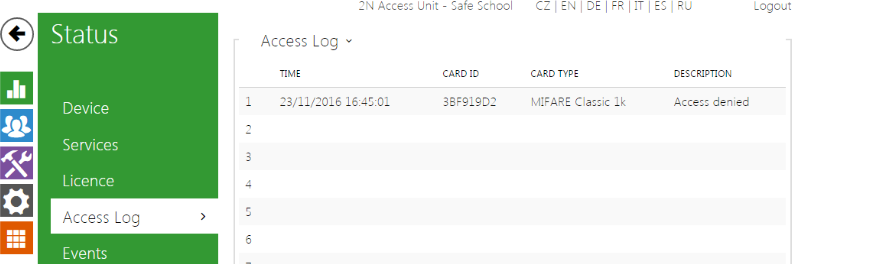
Figure 3: Access Log
If your reader is not powered by default, you can use external supply (12 V / 2 A DC) terminal of the 2N Access Unit. The wiring is shown in the figure 4 bellow.
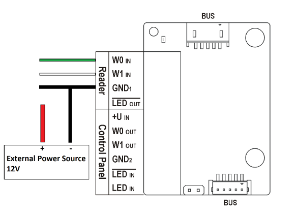
Figure 4: Wiring
Note
Wiegand module doesn't fit into the 2N Access Unit cover. There are many possibilities how you can place your Wiegand module:
- If you are using flush mounting box (Part No. 9155014), you can place Wiegand module in there. There is free space in the box which can be used.
- It is possible to use blind module (Part No. 9155039) into which the Wiegand can be placed. In this case you would need to use a 2-module frame.
- It is possible to place a Wiegand module into some box behind of the 2N Access Unit or in some other place, however the length of the Verso bus cable has to be max. 5m.
This procedure can be applied to:
- 2N Access Unit
- 2N Access Unit 2.0