Door section - How to configure it on the 2N IP intercoms
Since FW version 2.22 the intercoms of 2N IP intercoms family contain a new menu "Hardware->Door" in the web interface. This menu offers following:
- Even easier configuration of the 2N® IP intercoms. It concentrates all settings related to the physical door controlled by the intercom in one place.
- The installer in now able to setup a different global Entry and Exit rules and a different global modes of authentication (double authentication via code and RFID code, triple authentication via code, RFID card and Bluetooth and so on) instead of configuring it for each user.
- Configuration of the REX button is part of this menu.
- New integration with Genetec Synergis access control system.
Firmware version 2.22 requires 2N® Access Commander version 1.9.1 or higher, firmware version 2.23 requires 2N® Access Commander version 1.10 or higher, for closer details see here. Step by step FAQ with detailed description of this new menu including screens from the web interface itself can be found below.
Configuration of the Door section
Go to the section "Hardware->Door->Door". It offers the following settings:
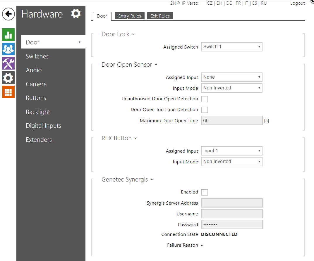
Door Lock
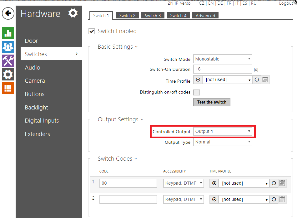
This section defines which switch from the section "Hardware->Switches" is used for the physical door lock (or door strike). You also need to configure a particular switch in that section (Switch 1 in the picture). Logic in this section stays the same. You just pick a particular Switch (in our case "Hardware->Switches->Switch 1") and choose a physical output for the parameter "Controlled Output" as shown in the picture below.
 Door Open Sensor
In this part you can configure all settings related to a door sensor (it can be the magnetic contact from 2N for instance, ordering no. 9159012).
- Assigned Input - Choose a physical input on the intercom where is the door open sensor connected. It can be either input on the main unit itself or on a card reader or on an I/O module.
- Input mode - Choose between two modes of the input. "Inverted" for normally closed button and "Non Inverted" for normally opened button.
- Unauthorised Door Open Detection - Enable this checkbox to track unauthorised door opening. Once intercom detects that the door was opened (via the assigned input and door sensor) but the assigned switch from the section "Door" was not activated, it generates an event "UnauthorisedDoorOpen" to the event log. This event can be pulled via the HTTP API and it is also visible in the 2N® Access Commander which can operate with this event further more.
- Door Open Too Long Detection - Enable this checkbox to detect when the door is opened too long (someone puts an obstacle in it's way and it can't be closed for instance). After the timeout "Maximum Door Open Time" from below is exceeded, an event "DoorOpenTooLong" is generated to the event log. This event can be pulled via the HTTP API and it is also visible in the 2N® Access Commander which can operate with this event further more.
- Maximum Door Open Time - Defines the timeout for the "Door Open Too Long Detection" checkbox.
REX Button
This section configures so-called request on exit button, which allows to open the door when exiting a building. Once the button is pressed, the door is opened.
- Assigned Input - Choose a physical input on the intercom where the REX button is connected. It can be either input on the main unit itself or on a card reader or an I/O module.
- Input mode - Choose between two modes of the input. "Inverted" for normally closed button and "Non Inverted" for normally opened button.
Genetec Synergis
This section allows integration with a part of the Genetec Security Center platform and in particular with the Genetec Synergis access system. The intercom FW contains the RIO protocol of Genetec which is used for the communication with the Genetec server. If configured, the intercom forwards an ID of every swiped card (or Bluetooth and finger print if the virtual card ID is used) to the server which has a database and it verifies whether it is valid or not. Based on that, the intercom will either open the door or not.
All you need to do in this section is enabling the "Enable" checkbox and fill in the "Synergis Server Address" with the actual IP address of your server and the credentials ("Username" and "Password"). The "Connection state" shows whether the connection is established successfully or not.
Configuration of the Entry Rules and the Exit Rules
If you are using the 2N® IP intercom together with the 2N® Access Commander then it is necessary to use at least version 1.9.1. This version does not have the new Door section yet, however it is fully compatible with the FW version 2.22 for the intercoms. The Door menu will be available in the version 1.11 of the 2N® Access Commander. Below you will find what exact parameters are configured by the 2N® Access Commander server.
The picture below shows the layout of the "Entry Rules menu". The parameters are explained below the picture.
 Entry Rules
This section serves for configuration of a multiple entry rules with a different authentication modes. Since version 2.22 the authentication modes are configured globally here and it is not possible to configure it for each user. Configuration of multiple authentication for each user from the previous FW version is not reflected here after the upgrade to version 2.22.
- Access Enabled - 2N® Access Commander does not affect this checkbox, after upgrade to 2.22 this checkbox is always enabled. If it is disabled by the user, then the server is not able to enable it again.
- Door Locking - Default state is "Unlocked". This is also not controlled by the 2N® Access Commander server in the current version. Version 1.11 will then allow to lock/unlock all the intercoms during a hazard situation.
- Access Profiles - This section allows configuration of multiple access rules. The Access Rule from the 2N® Access Commander (Zone+Group+Time profile) is applied on the 1st and the 4th row. As the intercom applies the first matching rule (starting from the top), you do not have to be worried that the 4th row will enable an access 24/7 as it does not have any time profile. The time profile for the 2nd and the 3rd row is not configured by the the 2N® Access Commander at the moment and you can configure it manually. Multiple authentication set for the zone is applied on this row, you can disable these rows by the checkboxes. The "Zonal code" checkbox is related to the parameter with the same name in the Advanced Settings. The checkbox enables opening of the door via this code. What this code is described below.
Advanced Settings
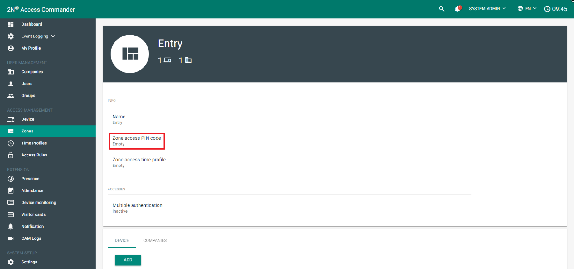
- Zonal code - You can set one global PIN code for the whole Zone in the 2N® Access Commander ("Zone Access PIN code" ). This code is then filled in here. It is highly recommended to set this parameter over 2N® Access Commander only! Where you can configure this code on the side of the server is shown below.
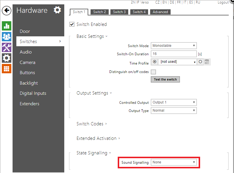
- Authentication Signalling - Acoustic signalisation for access events. You can pick from three options. "None" - no signal is played upon access event. "Short beep" - short beep is played for valid and invalid access events both. "Full" - acoustic signalisation of Switch you picked in the menu "Hardware->Door->Door->Door Lock" is applied. This also allows you to use your user sounds for the signalisation. Signalisation of the switch in our case is in the menu "Hardware->Switches->Switch 1->State signalling" as shown bellow.
- Virtual Card to Wiegand - In case you use the virtual card ID (you can add it to each user in the section "Directory->Users" and in the section "Access cards" on page of particular user), you can forward this ID to Wiegand interface by picking a group. Wiegand group for each Wiegand module can be configured in the section "Hardware->Extenders" for 2N® IP Verso and in the section "Hardware->Card reader" for the other 2N® IP intercoms.
- Silent Alarm Enabled - If enabled, you can add a virtual code higher by 1 then an user access code. So for instance if the access code is 0000 then the silent alarm will be triggered by 0001. You can operate with the Silent Alarm further more in the Automation section - event "SilentAlarm".
- Limit Failed Access Attempts - If enabled after 5 invalid access attempts it is not possible to access by any mean for 30 seconds.
Service cards
- Plus Card ID - Add one service card to add RFID cards to the Directory. Once you swipe the plus card any following card is added to the Directory if it is not full.
- Minus Card ID - Add one service card to delete RFID cards from the Directory. Once you swipe the minus card, any following card is deleted from the Directory.
Anti-Passback
- This feature is available only on firmware 2.24.
- System is checking where the user is according to attendance history and where the user is according to the used reader location.
If those places are different, access is granted. If those places are the same, anti-passback rule has been unset. - Soft mode - Anti-passback event is alerted, user can enter.
- Hard mode - Anti-passback event is alerted, user can´t enter.
Exit Rules
Exit rules are NOT affected by the 2N® Access Commander anyhow at the moment! As you can see in the picture below, the Exit rules have the same parameters as the Entry Rules. So besides the fact that nothing is being configured by the the 2N® Access Commander server, everything described above for the Entry rules is also applied here. There is just one difference. You have a checkbox for each Access rule, where you can define whether it should be possible to open the door via the REX button when this rule is applied.

Card reader configuration
The last thing you need to do is configuration of the card reader or readers (in case you use Entry and Exit rules both). You can configure the reader either in the section "Hardware->Extenders" for 2N® IP Verso or you can do it in the section "Hardware->Card reader" for the other 2N® IP intercoms. You need to define two things. The first is the parameter "Door" where you can pick whether the reader will be on the Entry or the Exit side. So the options are "Door Entry" and "Door Exit". The second thing is the parameter "Associated Switch" which defines which switch will be controlled by the card reader. You can pick one of the 4 switches in the section "Hardware->Switches" or the "Door Lock Switch" which was defined in the begging of this FAQ. In our case we use the Door Lock Switch.
