Induction loop - How to connect it with 2N IP Intercom
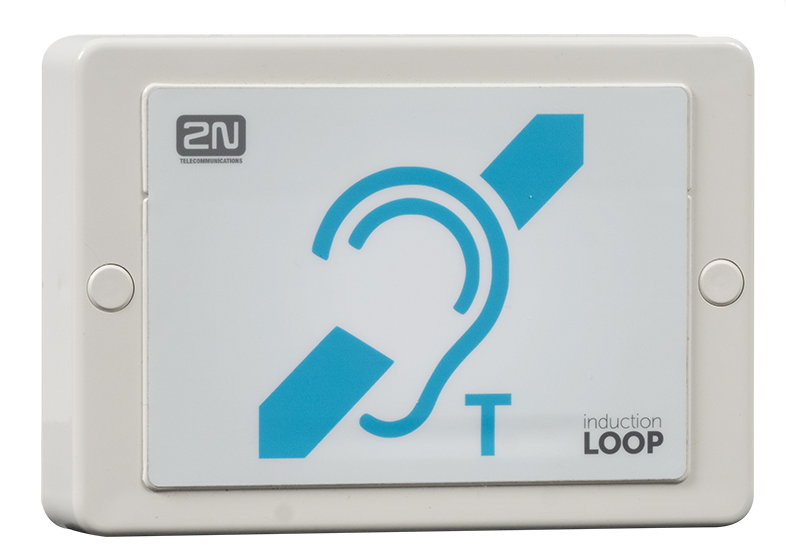
1) Product Description: The device is part of sound system installations for hearing impaired persons that are equipped with a special hearing aid capable of receiving reproduced sound via a magnetic field receiver. The system is defined by the IEC 60118-4 standard. Induction loop is supported by this products: 2N IP Verso, Force, Safety, Vario, Uni
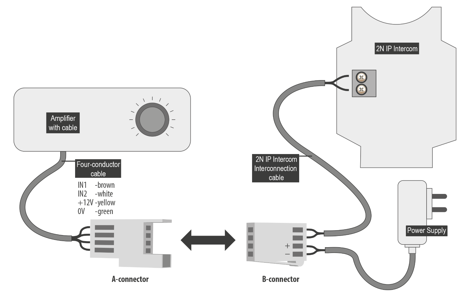
2) Installation: Amplifier Mounting, version for 2N IP Intercom
The induction loop amplifier can be wall mounted with the use of an internal induction loop where a signal covering is requested. Outdoor use is possible thanks to the IP65 covering. A four-wire cable of the length of one meter is mounted to the supplied product for easier connection to the intercom. In the cable are two wires for 12 V DC supply and two wires for signal input, the wires are connected into interconnection connector. If you shorten the cable, follow the colour marking. Before wall mounting run the cable through the hole that you have prepared. Then mark two mounting holes on the wall, through the amplifier front. Remove the amplifier and drill the mounting holes. Use the plugs and screws included in the delivery. Use a drill of the diameter of 6 mm. After fastening, cover the screws with the blanks supplied. Use the supplied connectors to connect the amplifier to the intercom and power supply. The A connector is connected to the amplifier four-wire cable. Insert a special intercom-connecting cable supplied with the amplifier and 12 V power supply outlets to the B connector. Connect the special cable to the intercom and connect the power supply to the mains. You can place the mated A and B connectors into the 2N IP Intercom cover. The connectors help you connect stripped cables. Open the connector by pushing a thin screwdriver onto the white spots at its front and close the connector by sliding the movable part through a side gap.
Finally, test the amplifier function using a suitable receiver for hearing impaired persons or magnetic field communication tester. No other settings are required.
3) Where to connect:
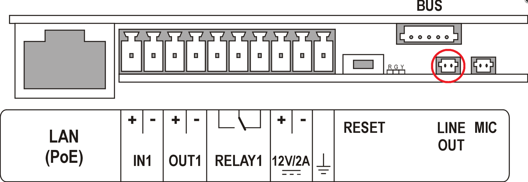 IP Verso
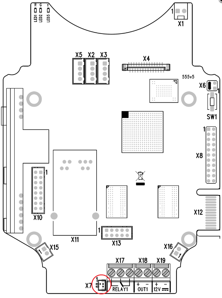
IP Force / Safety

IP Vario

IP Uni
4) Technical Parameters:
Supply voltage 8 – 18VDC
Transition to standby w/o signal 10 s
Input level - basic 100 mV – 6 Vrms
Input level - increased 1 V – 35 Vrms
Input impedance 2 kΩ parallel with 0.3 H
Output current, 1 Ω load, 2.2 Arms (sine wave)
full power output 1.6 Arms (pink noise)
Output current, 8 Ω load, 730 mArms sine wave signal
half power output 520 mArms pink noise signal
Output short-circuit resistance unlimited time
Frequency characteristics 100 Hz – 5KHz ±3 dB
Temperature range -20 - +50 °C
Covering IP65 (with round cable of 5 - 10 mm diameter)
Dimensions 144 x 100 x 31 mm
Weight 0,3 kg