Multicast Discovery - What is it good for
By default, the 2N® Indoor Touch is using multicast communication to be able to set up the connection towards the 2N IP intercoms. The multicast communication allows the device to reach any other device within the LAN network because L2 devices (switch) send the packet with the multicast destination IP address to all the interfaces. feature can be found in the 2N® Mobile application in the section settings->Multicast discovery.
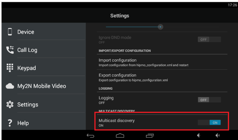
Figure 1
Multicast discovery enabled
By default the multicast discovery is enabled on the 2N® Indoor Touch. Info packet is sent towards the specific multicast address and reach all 2N IP intercoms within the LAN network. Info packets are used for pairing procedure between 2N® Indoor Touch unit and intercoms. Intercoms are sending multicast messages as well. These messages are being sent periodically and contain various types of information used for the proper function of the devices.
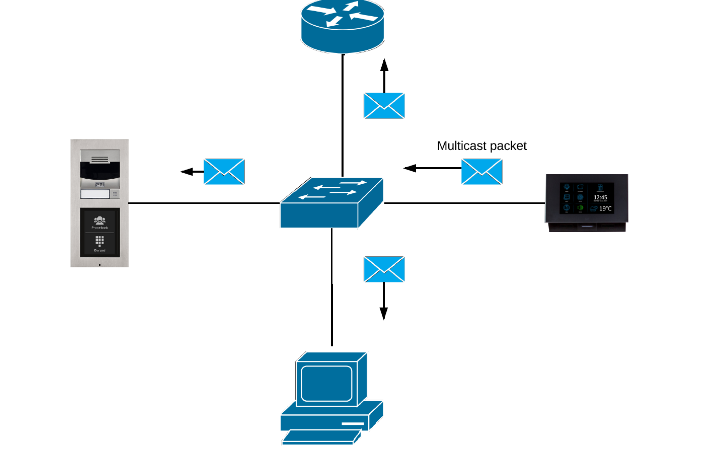
Figure 2
Multicast switching
The default behavior for L2 switches is to forward all multicast traffic to all ports on the switch. However this in general might cause the reduction of the bandwidth as the traffic is send also to hosts which do not want to receive multicast traffic. Due to this fact the IGMP snooping has been introduced in switches. There are 3 types of switches:
- L2 switch - just sending multicast traffic to all ports
- L3 - aware switch - IGMP snooping (further explained below) can be configured
- L3 switch - this switch is also able to act as router
Multicast discovery disabled
In this mode, 2N® Indoor Touch sends info packets in unicast always to the IP address of the 2N IP intercom observed and periodically to all the 2N Helios IP intercoms in the LAN device list. In the unicast mode, info packets are only sent to the 2N IP intercoms; no other 2N® Indoor Touch devices in the LAN are sent any info packets. This mode is beneficial in case that your switch does not support multicast or switching the multicast in wrong way.
Examples:
- Switch does not support IGMP snooping - as a result the network can be flooded by the multicast packets which contains video preview from the intercom and cause the significant reduction of the bandwidth.
- 2N® Indoor Touch is connected to the wifi - wifi router can block the multicast traffic becuase the TTL filed is equals to 1 which means that the packet cannot be sent further into the network and also some wifi devices has troubles to handle the multicast.
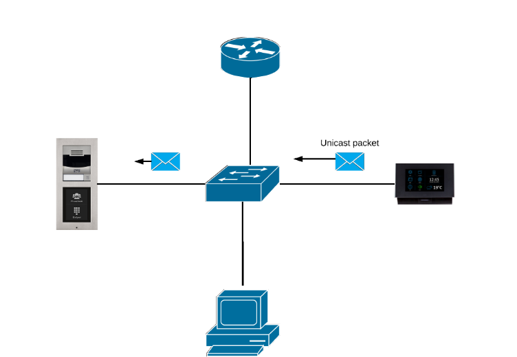
Figure 3
IGMP snooping
IGMP protocol is a mechanism between hosts and routers used for the dynamic registration of hosts to a specific multicast group. Hosts joins to multicast group by sending IGMP messages to their local router. Router listen IGMP messages and periodically sends queries to discover which groups are active or inactive. IGMP snooping is a mechanism that is implemented on L3 aware and on some L2 switches. Switch "snoop" some L3 information such as IGMP join/leave messages in the IGMP packets send between the host and router. The switch is controlling IGMP messages because the multicast is sent towards all the interfaces by default and if there is a video stream send, which will be using significant amount of the bandwidth, the switch would flooded all the interfaces with this traffic, which could cause the reduction of the overall performance of the network. With the IGMP snooping enabled the switch is sending the multicast traffic only towards interfaces, from which the IGMP group membership report message has been sent.
- If switch receive the IGMP host report from host to join a specific multicast group – it adds the switch physical port number where the host is connected to multicast table.
- If switch receive the IGMP leave message from the host – its removes the table entry of the host.
However IGMP control messages are send as packets (L3 layer), so it is not possible to distinguish those messages from the rest of multicast traffic on switch. L2 switch can only identify that the frame is the multicast based on the MAC address. In case of multicast frame, The multicast IP address is mapped to the destination MAC address. First half (24 bits) of the MAC address is always the same (01:00:5E:XX:XX:XX) and the rest is based on the last 23 bits of the multicast IP address. This means that the switch needs to check each multicast frame if it contains IGMP control message or not. This means that the low-end switches might have an issue with the speed in case of high rates due to a slow CPU. High end switches has Application Specific Integrated Circuits (ASICs) that can perform IGMP check in hardware.
Multicast network setting and 2N® Indoor Touch
As described in this article, there are many types of the switches so there is no universal rule how to configure your network equipment. As already mentioned, in general L2 switches should send multicast traffic to all ports. Some L3 switches has IGMP snooping enabled by default some not. If the IGMP snooping is disabled, the switch should send a multicast traffic to all ports.
Note
The IGMP snooping should be enabled to allow the switch send the multicast traffic to all ports. However some switches are not checking IGMP messages and just adding physical ports to its Multicast table based on the multicast traffic. Because it is possible to get a multicast address from the destination MAC address, the switch will create a multicast table with specific multicast groups or simply the IGMP snooping is not implemented correctly. This feature is also called IGMP snooping on some switches. In such cases the IGMP snooping needs to be enabled.
Consequences of incorrect multicast settings:
- Video preview does not work
- It is not possible to open doors from the unit
- You are not able to see other 2N devices in the device list (Figure 4)

Figure 4
How to resolve it:
- Enable IGMP snooping on the switch if disabled
- Disable IGMP snooping on the switch if enabled
- Try to manually create IGMP snooping groups
- There will be two IGMP snooping groups ( 235.255.255.241:8004 and 235.255.255.240:8002)
- Add all interfaces where 2 devices are connected to a newly created IGMP snooping groups
- There is also option to change the IGMP version in some switches - as mentioned above we do not use IGMP protocol so the switch should forward traffic to all ports however you can try to use IGMPv1 or IGMPv2 in case that the above mentioned points wont resolve the issue