Configuration - How to set 2N® VoiceBlue MAX
In firmware version 1.20 we have changed the way how call routing is set up. This FAQ is going to show you how to set 2N® VoiceBlue MAX in firmware 1.20+.
If you are currently using firmware that is older than version 1.20 (1.19 and lower) please upgrade your firmware version or go here: older FW version, where you will find FAQ on how to set 2N® VoiceBlue MAX in older FW version.
- 2N® VoiceBlue MAX is a device that helps directly interconnect the SIP-supporting VoIP network with GSM networks and can be used for direct connection with a SIP telephone set. Besides, 2N® VoiceBlue MAX contains 4x FXS ports for analogue telecommunication equipment. The voice mode, i. e. outgoing and incoming calls, is the basic function of the gateway. 2N® VoiceBlue MAX is equipped with all voice mode functions and provides the highest user comfort. In addition to voice transmission, 2N®VoiceBlue MAX enables you to send and receive text messages (SMS). You can use the web interface or AT commands for all the gateway settings. The programmable parameters are set in such a way that you can make calls the moment you connect the system to the Ethernet, connect an antenna and insert the SIM card. 2N® VoiceBlue MAX can be combined with the 2N® Mobility Extension service (remote GSM extension) for up to 8 users.
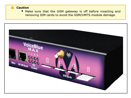
SIM Card Placement
Insert the SIM cards into one of the four SIM holders on the 2N® VoiceBlue MAX front and make sure that the chip contacts are at the front bottom. The SIM holders are equipped with the push&pull technology for facilitation.
How to connect to the 2N® VoiceBlue MAX
- The configuration of the 2N® VoiceBlue MAX is done via the web interface
- In the following chart there are the factory settings for the key configuration parameters of the 2N® VoiceBlue MAX
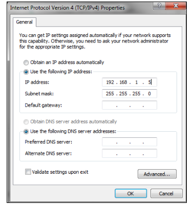
- Connect the 2N® VoiceBlue Next via Ethernet cable directly to the computer. Change the IP address setting in the configuration of your PC (e.g. 192.168.1.5 and Subnet Mask 255.255.255.0)
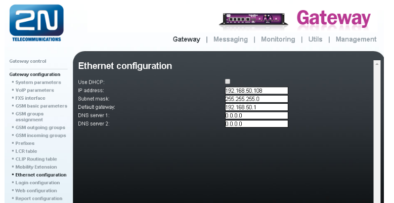
- Open your web browser and enter the default IP address of GSM gateway 192.168.1.2 with the default credentials (Admin/2n). If web page does not appear, then do a factory reset of the gateway with RESET button on the front panel. Press it for 10 seconds. Afterwards the gateway restarts and you can reload the page.
- In the Gateway configuration / Ethernet configuration menu you are able to change the IP address.
How to set up the Call Routing
In the VoiceBlue MAX calls can come from the FXS Ports or from the VoIP port and calls are routed to any GSM/UMTS port according to the LCR (Least Cost Routing) table. If the GSM port is busy, other ports are checked automatically for availability (depending on the configuration) and in case if an allowed outgoing port is not available, the outgoing call will be rejected.
The LCR algorithm identifies the outgoing call type, current time tariff rate, day in a week, eventually free minutes of GSM providers and routes outgoing calls accordingly. Incoming calls from GSM networks are routed directly either to the FXS Ports or to the defined SIP address, or the DISA function is activated. Furthermore, calls can be routed according to the CLIP (caller's telephone number). And the CallBack service is also available.
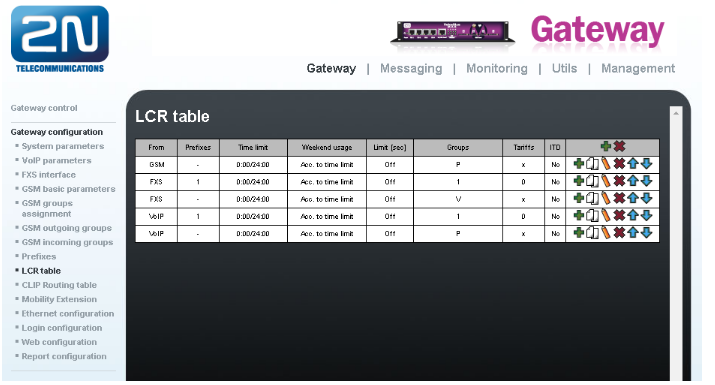
If you want to check current settings of call routes, go to the Menu Gateway Configuration / LCR table
How to set up the LCR Table
The LCR (Least Cost Routing) helps you select outgoing call routes according to the port the outgoing calls is originating from (FXS, GSM or VoIP), called subscriber's number (or some prefix), time of the day and weekdays.
Whenever a call is being done, the LCR table is searched sequentially from top to bottom. If the called destination prefix matches the network prefix included in the List of networks table (and designated as Network number in the LCR table), the call is routed according to the routing group parameters (Groups in the LCR table) as set in the GSM outgoing groups table. The call will be connected via the GSM module which was assigned to the GSM outgoing group in the Assignment to GSM groups table.
Therefore, you need to set and configure:
- GSM Group Assignment
- GSM Outgoing Groups
- Prefixes
Example
Let’s say we have SIM cards of two GSM operators:
- Operator 1: Using the following prefixes (602, 606, 607, 723, 724) and it requires you to dial the number from your mobile phone with the international prefix (+420). All numbers have nine digit length with the operator prefix but without the international prefix.
- Operator 2: Using the following prefixes (901, 902, 907, 909) and requires you to dial the number with the prefix (+420). All numbers have nine digit length with the operator prefix and without “+420”.
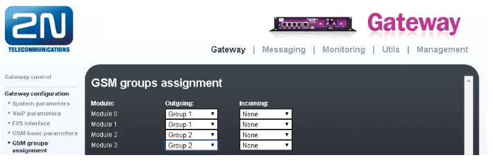
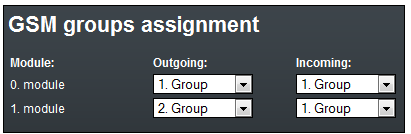
- GSM Group Assignment
- First we have to go to the menu Gateway Configuration / GSM Group Assignment and assign modules to two GSM outgoing groups (for each operator). Let's assume that
- Module 0 and 1 will have SIM cards from Operator 1 (Outgoing Group 1)
- Module 2 and 3 will have SIM cards from Operator 2 (Outgoing Group 2)
Configuration of GSM outgoing groups
You are able to set up different settings for each GSM group (CLIR, free minutes, Virtual ring tone, roaming and others).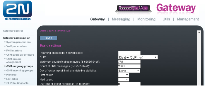
Prefix lists
We have to create two network lists, the first one for both of the Operators.
- Operator 1 network list:
We configure the normalisation of Called party number in the Table of replaced prefixes (the number in front of the slash mark is replaced by number behind the slash mark, if there is not any number in front of the slash mark it equals to “everything”).
We also have to fill in the Table of prefixes with all prefixes of the Operator 1. Because all numbers are 9 digits length, it is not necessary to specify each prefix, we can use the parameter Default count of digits and fill there the value 9.
The Table of replaced prefixes, Table of accepted prefixes and Digits count must correspond with the called number and it leads to the match in prefix list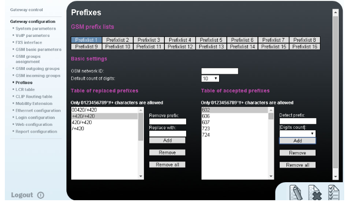
- Operator 2 network list:
We configure the normalisation of Called party number in the Table of replaced prefixes (the number in front of the slash mark is replaced by number behind the slash mark, if there is not any number in front of the slash mark it equals to “everything”). We also have to fill in the Table of prefixes with all prefixes of the operator 2. Because all numbers are 9 digits length, it is not necessary to specify each prefix, we can use the parameter Default count of digits and fill there the value 9.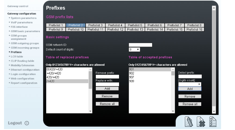
- Operator 1 network list:
LCR Table
We have to configure rows in the LCR table where we bind together GSM Outgoing groups with Prefix lists and ports where call is originating.
Please note that LCR table is searched sequentially from top to bottom. So position of each rule in LCR table is important. If there is a match found in a LCR rule than the call is routed to the destination specified in that rule. All other rules that are after the successful one do not matter.
In default LCR table looks like this: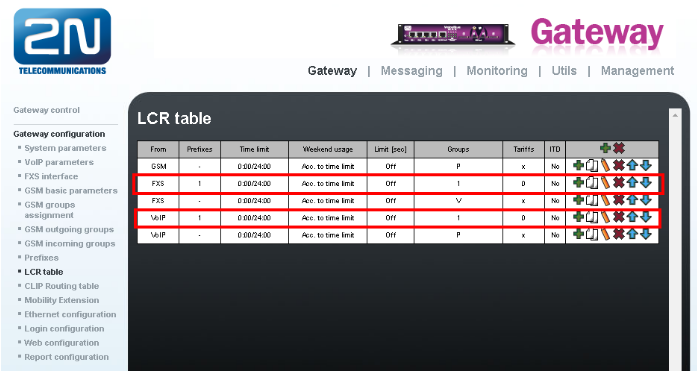
Where each line means following:
- 1st line - all calls from GSM are going to be routed to FXS interfaces
- 2nd line - calls from FXS ports, where called number matches prefix list 1, will be routed to GSM through GSM outgoing group 1
- 3rd line - calls from FXS ports, where called number matches any prefix list, will be sent to VoIP
- 4th line - calls from VoIP, where called number matches prefix list 1, will be routed to GSM through GSM outgoing group 1
- 5th line - calls from VoIP, where called number matches any prefix list, will be sent to FXS interfaces
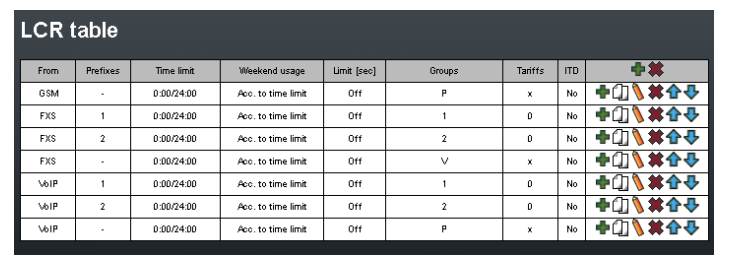
To complete setting of our scenario we need to add 2 more lines (or only 1 based on if you are calling only from FXS or only from VoIP). We already have 2 lines that are routing outgong calls from FXS ports to GSM outgoing group 1 and calls from VoIP to GSM outgoing group 1. We need to add only lines for outgoing GSM groups 2.
- Add rule for calls from FXS to GSM outgoing group 2 (called number must match Prefixlist 2)
Click on ADD button to add new line and configure it for Operator 2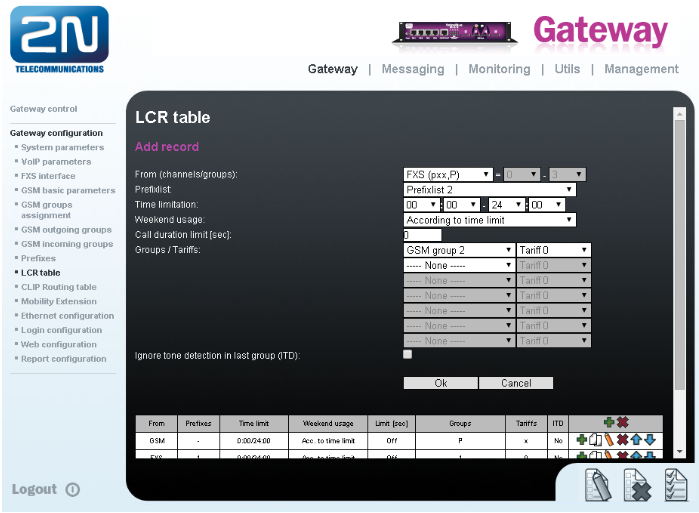 Click on OK and move the LCR rule into position under 2nd line.
 - Add rule for calls from VoIP to GSM outgoing group 2 (called number must match Prefixlist 2)
Click on ADD button and add new line and configure it for Operator 2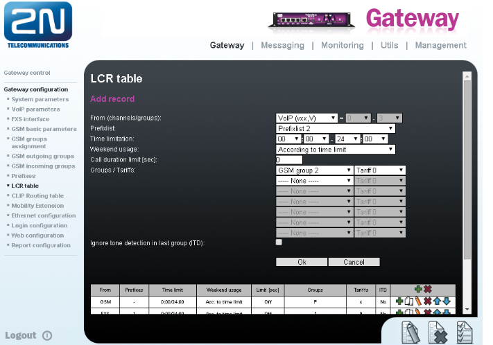 Click on OK and move the LCR rule into position before the last line
Now your LCR table should look like this:
If you want to find out more information about LCR table please go to following FAQ: LCR table in FW 1.20 where you can find more information on how to set LCR table
How to set up connection to the opposite device (PBX)
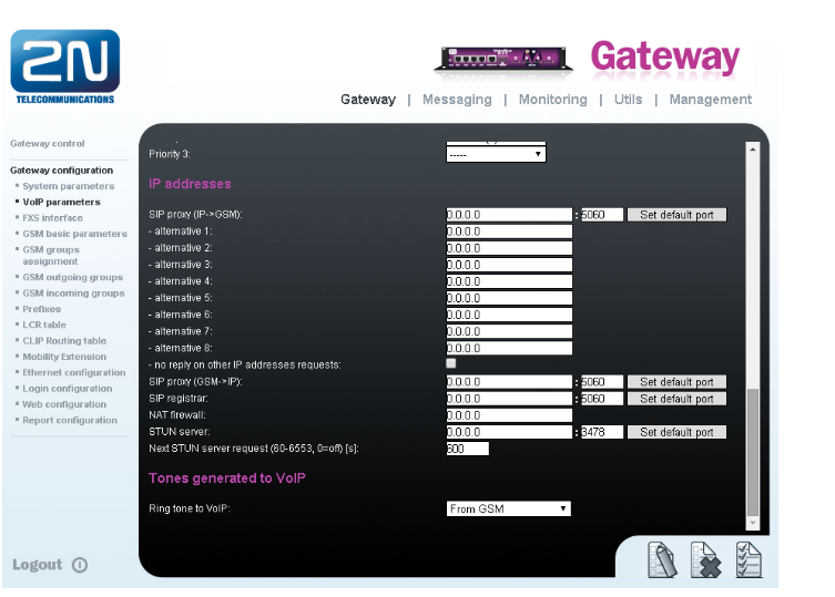
- For the settings of the trunk between the 2N® VoiceBlue MAX and your PBX you need to configure SIP proxy (GSM→IP) for GSM incoming calls. SIP proxy (IP→GSM) is designed for security and limitation of communication only on your PBX. You can specify the IP address and port from which SIP packets will be accepted.
- In case you leave there 0.0.0.0 in SIP proxy (IP->GSM), the gateway will be open for traffic from all IPs. !!! This can lead to misuse of equipment by an unauthorised person !!!
Incoming calls
- For incoming calls you can define 2 groups with the different behaviour and assign them to the GSM modules. The settings are similar with GSM groups assignment for outgoing calls.
- In GSM incoming groups you can define the behaviour for each GSM incoming group. Choose the mode to Reject, Ignore, Accept incoming calls or Callback.
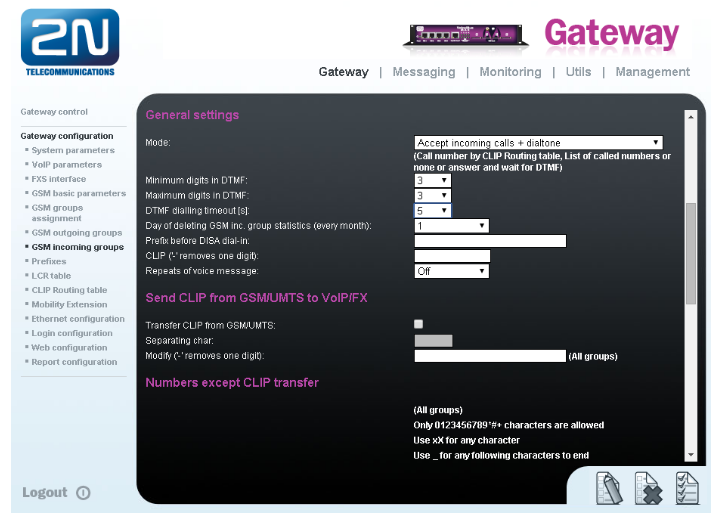
- In the mode Accept you can define the list of called numbers which will be automatically dialled after DTMF dialling timeout in case that the customer does not press any button within the given time. From the configuration you can see 5 seconds for DTMF dialling and after that the call will be routed to the extension 100 in your PBX (if you set up SIP proxy (GSM->IP) in VoIP parameters). If you want immediate connection then set DTMF dialling timeout to 0.
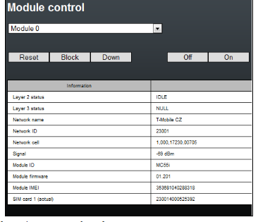
SIM cards
In the Gateway control and module control you can see the status of the SIMs. The recommendation for quality of the signal is between -65 and -85dBm.
- The logged SIM card is indicated by the led diode switched off on the 2N®VoiceBlue MAX