2.2 Mechanical Installation
Surface Mounting
What you need for mounting:
- 2N® IP Base plus appropriate frames
- LAN connection, UTP Cat5e or better with RJ-45 connector
- 802.3af PoE or 12 V DC / 2 A power supply
Before using this product, please read the instruction manual and follow the instructions and recommendations contained therein.
Installation procedure:
- Choose a location easily accessible to users.
- As the intercom is black, do not install it in direct sunlight to avoid overheating.
- Verify the cable connecting options – the device has two grommets towards the wall at the bottom.
- Prepare the cables connected to the LAN as well as the power supply and line to the lock or other accessories if necessary.
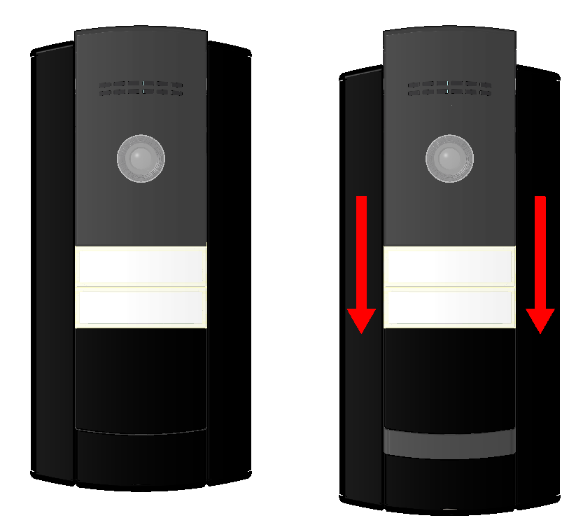
- Remove the metal frame of the device, open the lower blank module as pointed by the arrows and insert all the cables. Put the cables through the grommets. The manufacturer is not liable for defects caused by loss due to insufficient sealing.
- Fit the device to the backplate. You can use a drilling template; download here.
- Plug in the cables, check the functionality of the device.
- Replace the blank module and attach the frame.
- The figures below show frame demounting and position of the mounting screws.
 |
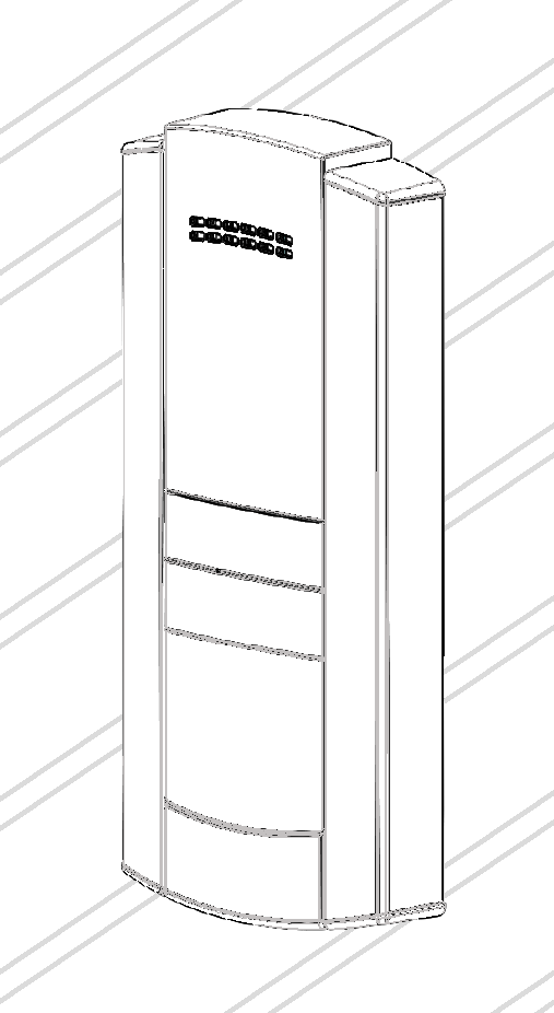
Frame Demounting. First use the torx handle enclosed to remove the screw that fits the frame to the 2N® IP Base structure.
|
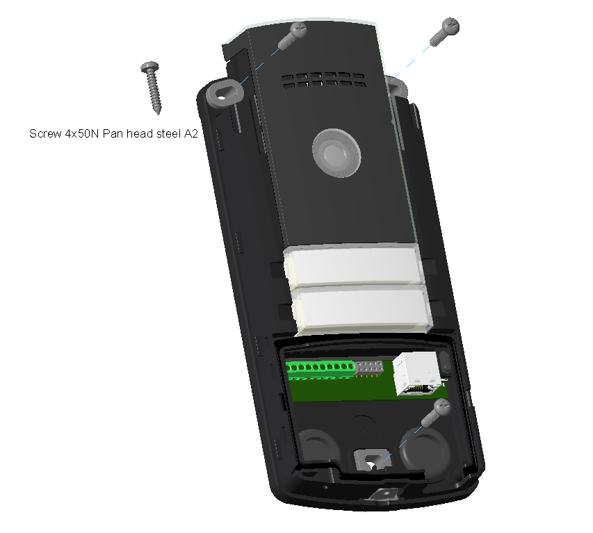
Position of Mounting Screws on 2N® IP Base
 |
The device is intended for surface mounting, for this type of installation the device itself is sufficient. A mounting backplate can be used (Part. No. 9156020) for uneven surfaces and easier installation. For mounting backplate installation, follow the mounting backplate instructions.
Caution
- After removing the front end cap at the lower part of the intercom make sure that there is no dirt on gaskets and connectors.
- The warranty does not apply to the product defects and failures arisen as a result of improper mounting (in contradiction herewith). The manufacturer is neither liable for damage caused by theft within an area that is accessible after the attached electric lock is switched. The product is not designed as a burglar protection device except when used in combination with a standard lock, which has the security function.
- When the proper mounting instructions are not met, water might get in and destroy the electronics. It is because the communicator circuits are under continuous voltage and water infiltration causes an electro-chemical reaction. The manufacturer’s warranty shall be void for products damaged in this way!
Mounting Principles
Caution
Before starting the mechanical installation on a selected place, make sure carefully that the preparations connected with it (drilling, wall cutting) cannot damage the electrical, gas, water and other existing wires and pipes.
- Make sure that the diameter of the dowel holes is accurate to avoid falling out of the dowels! Use the mounting glue to secure the dowels if necessary. Make sure that the depth of the dowel holes is accurate! Do not use low-quality dowels to avoid their pulling out of the wall!
- Never turn 2N® IP Base to align the box assembly after mounting. Make sure that the flush mounting boxes have been installed accurately.
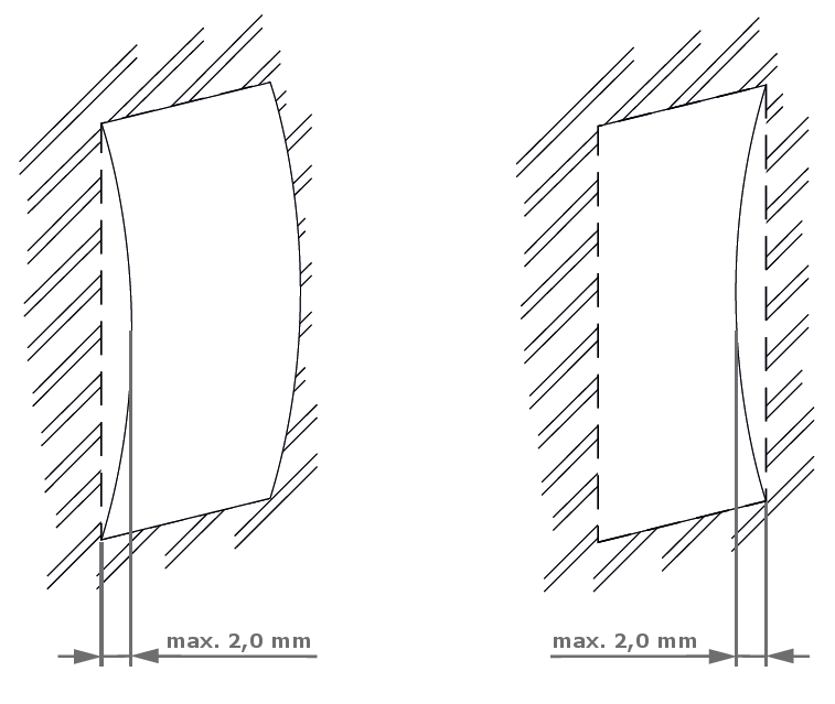
- Make sure that the surface mounting place is perfectly flat with the maximum inequality of 2 mm (e.g. desk materials, glass, cut stone etc.). If the place is not flat, use mounting backplate Part No. 9156020 or equal the wall surface.
 |
Tip
Video Tutorial: 2N IP Base Installation guide