2.4 Extending Module Connection
2N IP Base allows to connect following extending modules:
Module Bus Interconnection
Caution
- In case the firmware versions of the module to be connected and the main unit are incompatible, the module will not be detected. Therefore, it is necessary to update the device firmware after the modules are connected. Use the device web interface in the System > Maintenance > System configuration section for firmware upgrade (see Configuration manual for 2N IP intercoms).
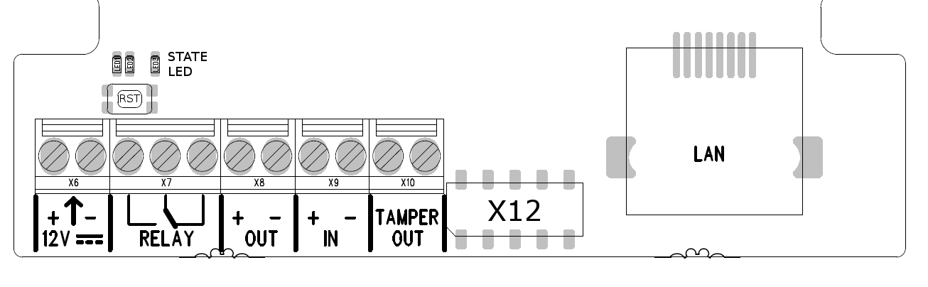
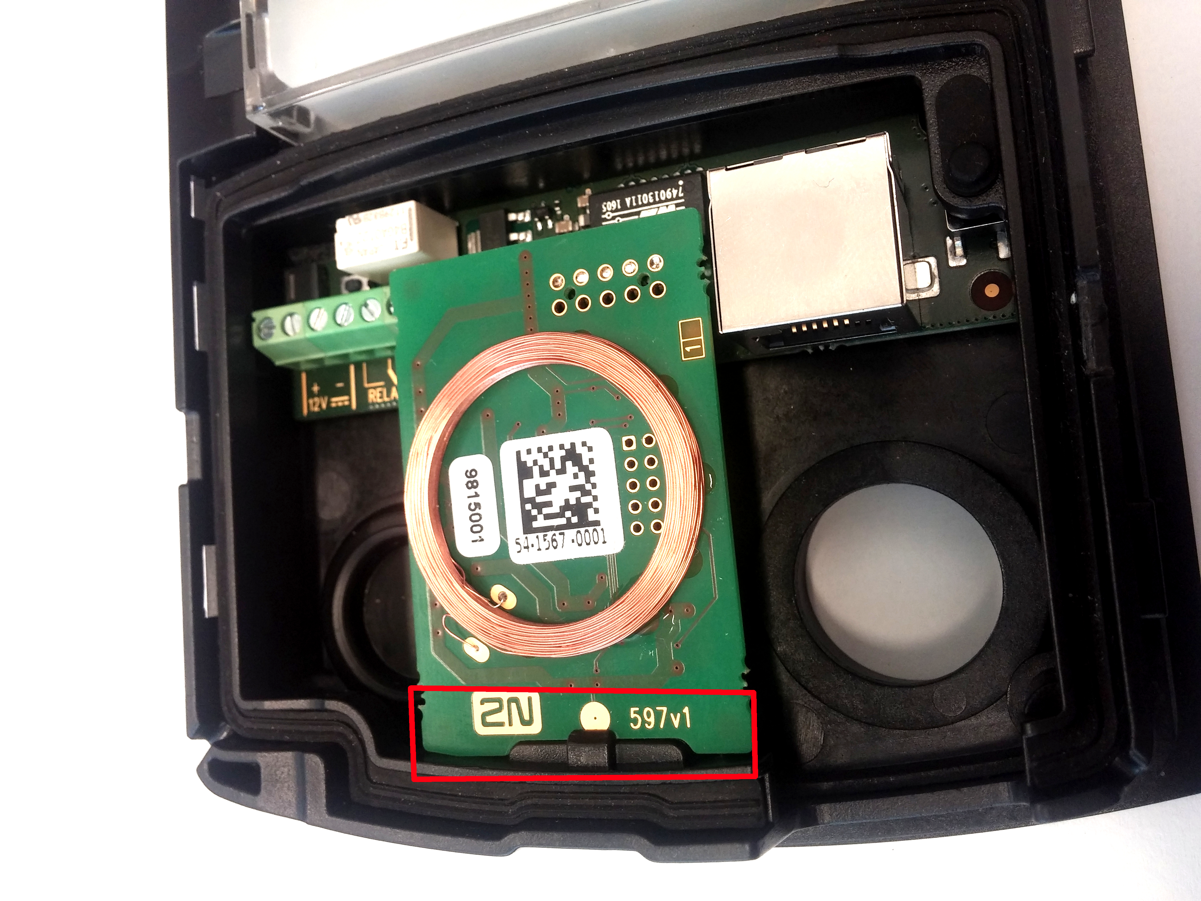
All modules 2N IP Base, are connected via connector X12, the position of this connector is shown in Fig. Before connecting RFID card reader it is suitable to disconnect 2N IP Base from the power supply. Only one module can be connected at a time.
 |
How to install modules:
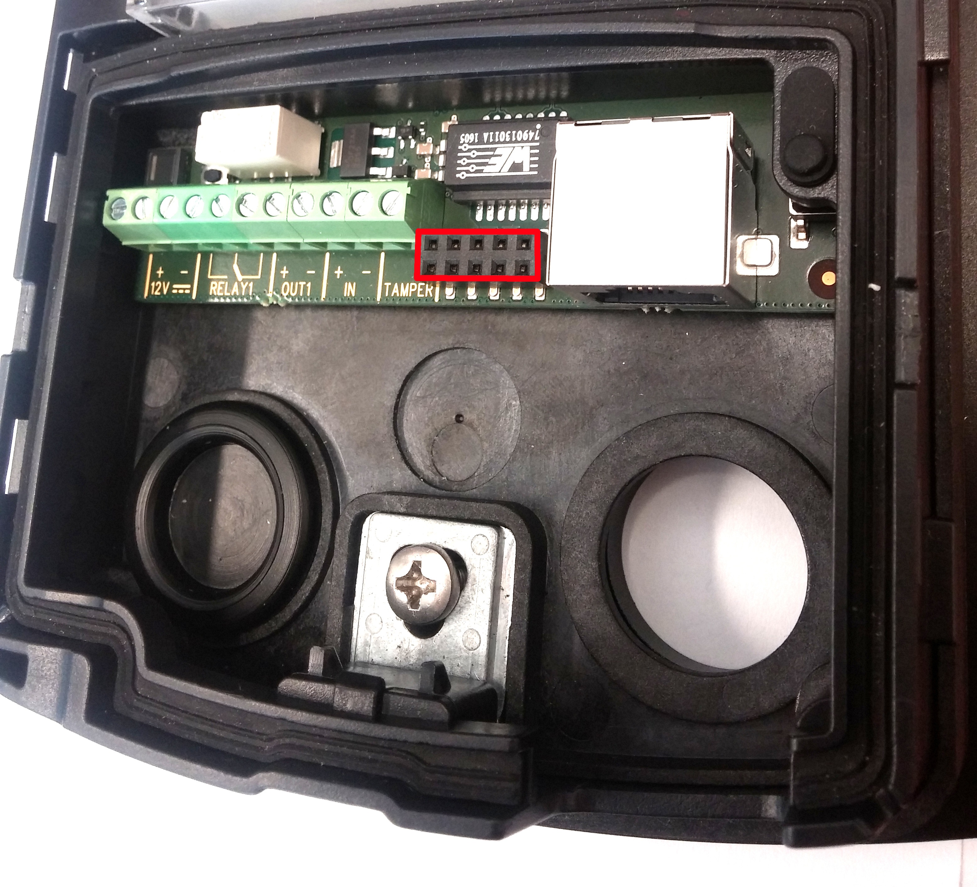
1) On the picture there is a highlighted connector X12. This connector is designed to connect the module to the main unit.
 |
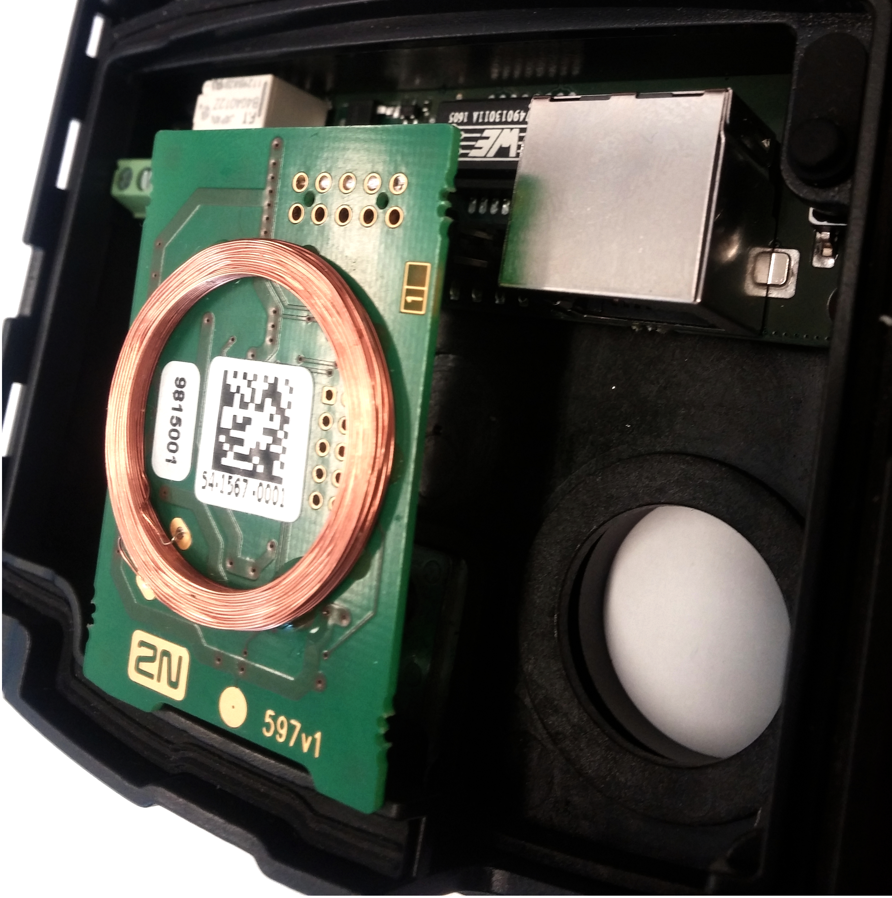
2) Insert the module of card reader into the shown connector.
 |
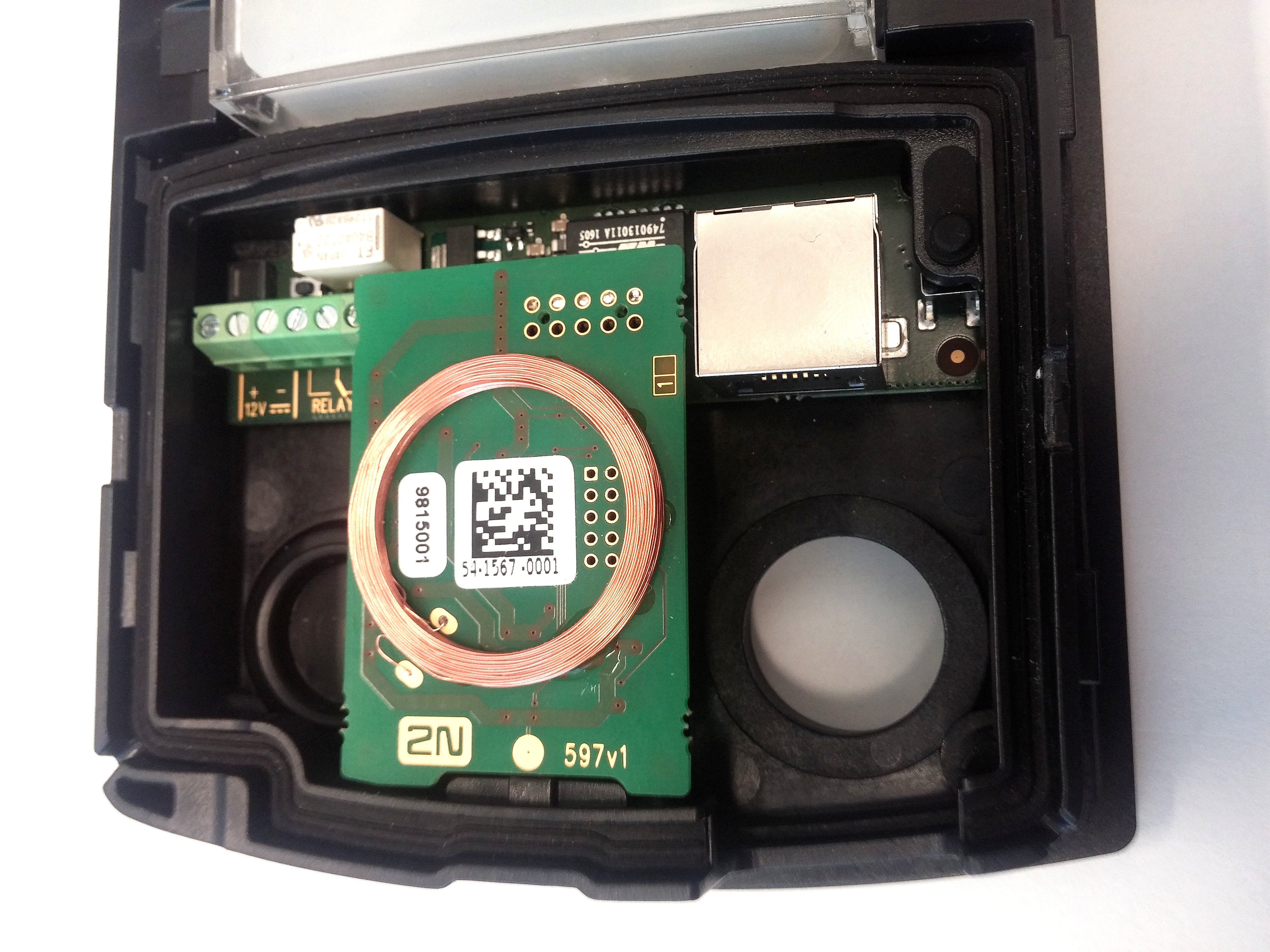 |
3) As the last, it is necessary to fix the module using tabs built into the structure of
2N IP Base. This tab is highlighted in the following picture by the red rectangle.
 |
Module Power Supply
All modules 2N IP Base are powered via connector X12.
RFID Card Reader Module 125 kHz
The 125 kHz RFID Card Reader (Part No. 9156030) is one of the 2N IP Base intercom elements and is used for reading RFID card Ids in the 125 kHz band.
The following RFID cards can be read:
- EM4xxx
RFID Card Reader 13.56 MHz, NFC/HCE
The 13.56 MHz RFID Card Reader (Part No. 9156031) is one of the 2N IP Base intercom elements and is used for reading RFID card Ids in the 13.56 MHz band.
The following RFID cards can be read (only card serial number is read):
- ISO14443A (MIFARE DESFire)
- PicoPass (HID iClass)
- FeliCa
- ST SR(IX)
- 2N Mobile Key
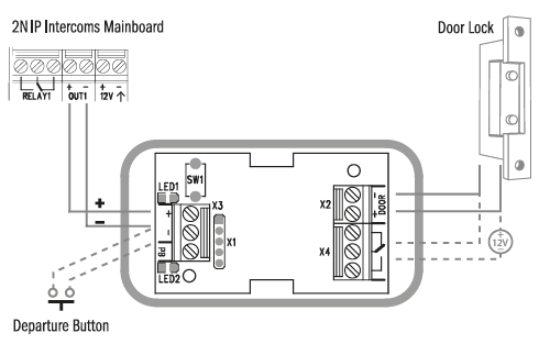
Security Relay
The 2N Security Relay (Part No. 9159010) is used for enhancing security between the intercom and the connected electric lock. The 2N Security Relay is designed for any 2N IP intercom model with firmware versions 1.15 and higher. It significantly enhances security of the connected electric lock as it prevents lock opening by forced intercom tampering.
 |
Function:
The 2N Security Relay is a device installed between an intercom (outside the secured area) and the electric lock (inside the secured area). The 2N Security Relay includes a relay that can only be activated if the valid opening code is received from the intercom.
Specifications:
Passive switch: NO and NC contacts, up to 30 V / 1 A AC/DC
Switched output:
- Where the security relay is fed from the intercom, 9 to 13 V DC is available on the output depending on the power supply (PoE: 9 V; adapter: source voltage of minus 1 V) / 400 mA DC.
- Where the security relay is fed from an external power supply, 12 V / 700 mA DC is available on the output.
Dimensions: 56 x 31 x 24 mm / 66.5 x 32.5 x 20.5 mm
Weight: 20 g / 24 g
Installation:
Install the 2N Security Relay onto a two-wire cable between the intercom and the electric lock inside the area to be secured (typically behind the door). The device is powered and controlled via this two-wire cable and so can be added to an existing installation. Thanks to its compact dimensions, the device can be installed into a standard mounting box.
The Security relay is designed with holes for surface anchoring. It is recommended that a screw of the diameter of 3 mm with a lens head of the diameter of 6 mm is used. Using a countersunk head may cause irreversible damage to the plastic cover!
Connection:
Connect the 2N Security Relay to the intercom as follows:
- To the intercom active output (OUT1)
Connect the electric lock to the 2N Security Relay output as follows:
- To the switched output.
- To the passive output in series with the external power supply.
The device also supports a Departure button connected between the ‘PB’ and ‘- HeliosIP/IP Intercom’ terminals. Press the Departure button to activate the output for 5 seconds.
Status signalling:
| Green LED | Red LED | Status |
|---|---|---|
| blinking | off | Operational mode |
| on | off | Activated output |
| blinking | blinking | Programming mode – waiting for initialisation |
| on | blinking | Error – wrong code received |
Configuration:
- Connect the 2N Security Relay to the properly set intercom switch output; refer to the Configuration manual for 2N IP intercoms. Make sure that one LED at least on the 2N Security Relay is on or blinking.
- Press and hold the 2N Security Relay Reset button for 5 seconds to put the device in the programming mode (both the red and green LEDs are blinking).
- Activate the intercom switch using the keypad, telephone, etc. The first code sent from the intercom will be stored in the memory and considered valid. After code initialisation, the 2N Security Relay will pass into the operational mode (the green LED is blinking).
Caution
- In case of resetting the factory default settings on a device with a version of firmware 2.18 or higher it is necessary to reprogram the 2N Security Relay using the instructions above.
Connection:
|
Tip
Video Tutorial: Security Relay Installation and Configuration