2.3 Electric Installation
This subsection describes how to connect 2N IP Safety into your Local Area Network (LAN) and how to connect supply voltage and the electric lock.
- PCB Connectors
- LAN Connection
- External Power Supply Connection
- Electric Lock Connection
- Factory Default Resetting (PCB version 555v4 and higher)
- Factory Default Resetting (PCB version 555v3)
- Factory Default Resetting (PCB version 555v2)
- Grounding
- Mounting Completion
- Available Switches
Caution
- The device must be part of the electrical system of the building.
PCB Connectors
Picture shows the lay-out of connectors on the 2N IP Safety printed circuit board (PCB). Cables, accessories and other system components are connected to connectors X1 through X22.
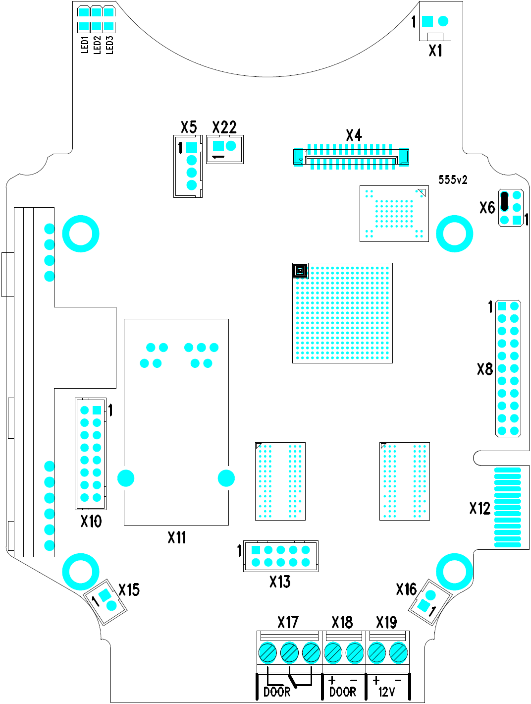 |
2N IP Safety Connectors, PCB Version 555v2
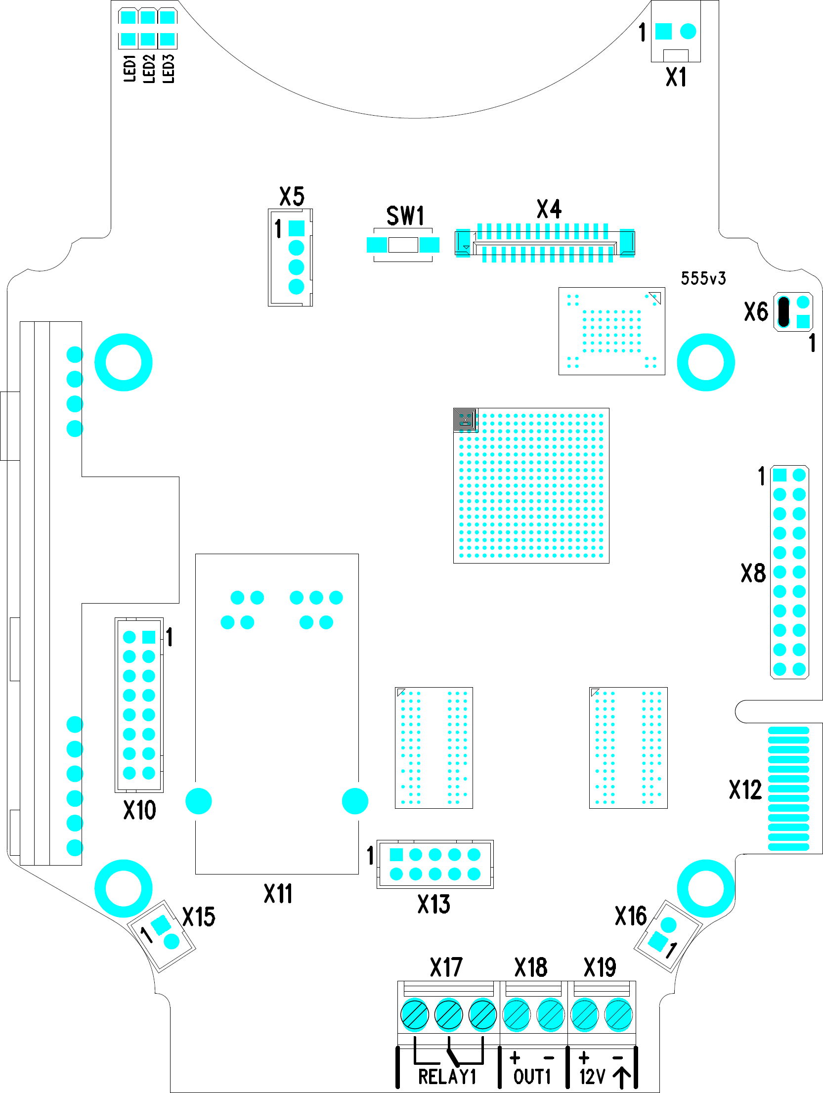 |
2N IP Safety Connectors, PCB Version 555v3
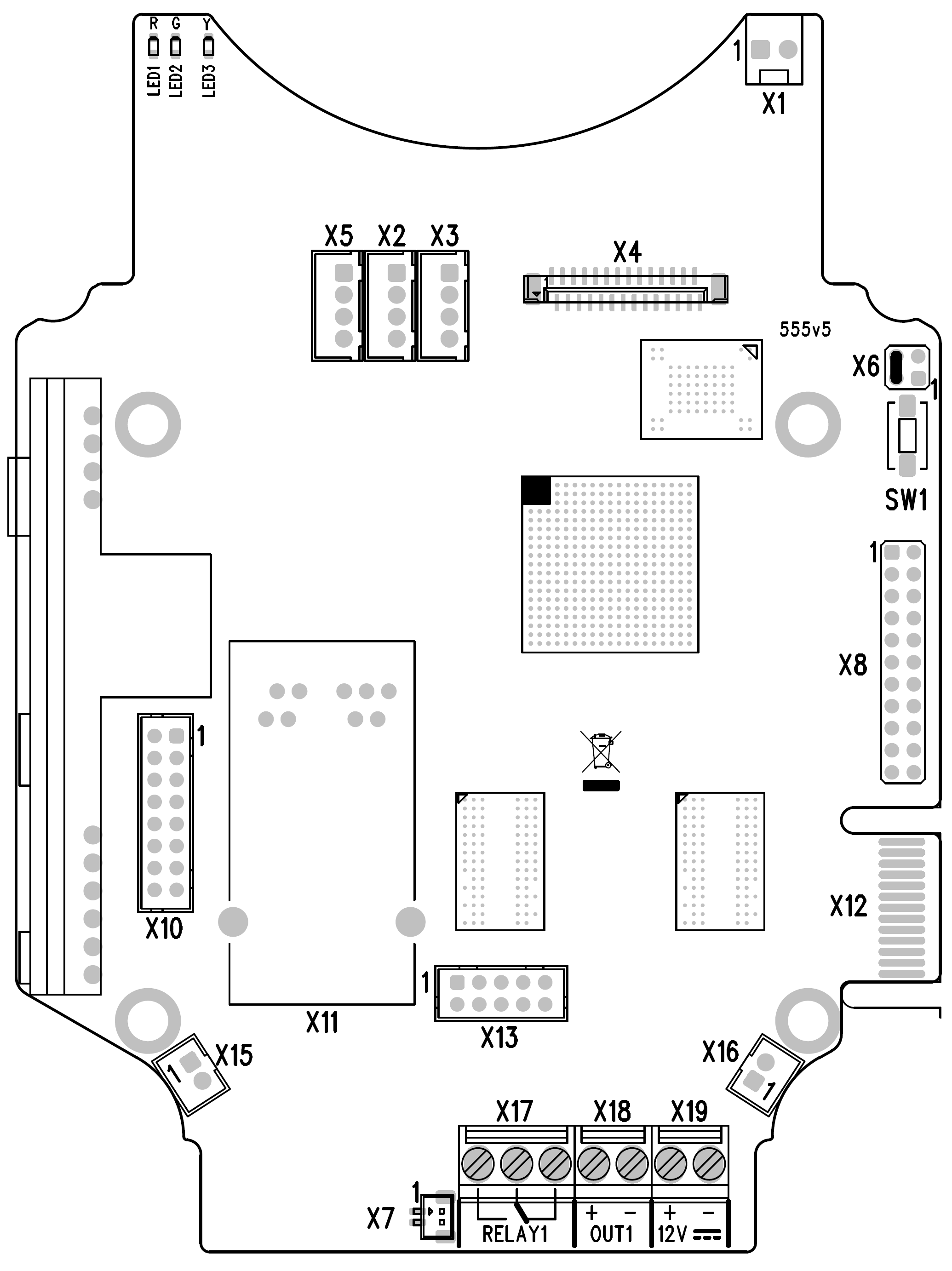 |
2N IP Safety Connectors, PCB Version 555v5
Description of Connectors:
- X1 – Loudspeaker
- X4 – Camera module
- X5 – Button 1
- SW1 – Reset button (555v3 and higher versions only)
- X6 – Configuration jumpers
- X7 – Induction loop output. Connector type JST SHR-02V-S.
- X8 – Extending module (RFID card reader or additional switch)
- X10 – Buttons 1 through 4
- X11 – LAN
- X12 – Servicing connector
- X13 – Keypad module
- X15 – Left-hand microphone
- X16 – Right-hand microphone
- X17 – Relay NO and NC contact. Used for connection of non-critical devices only (lights, e.g.).
- X18 – 12 V / 600 mA switched output
- X19 – 12 V / 1 A DC power input
- LED1/2 – System status indicators
- LED3 – LAN connection activity indicator
Tip
- Output wiring diagram for Relay terminals
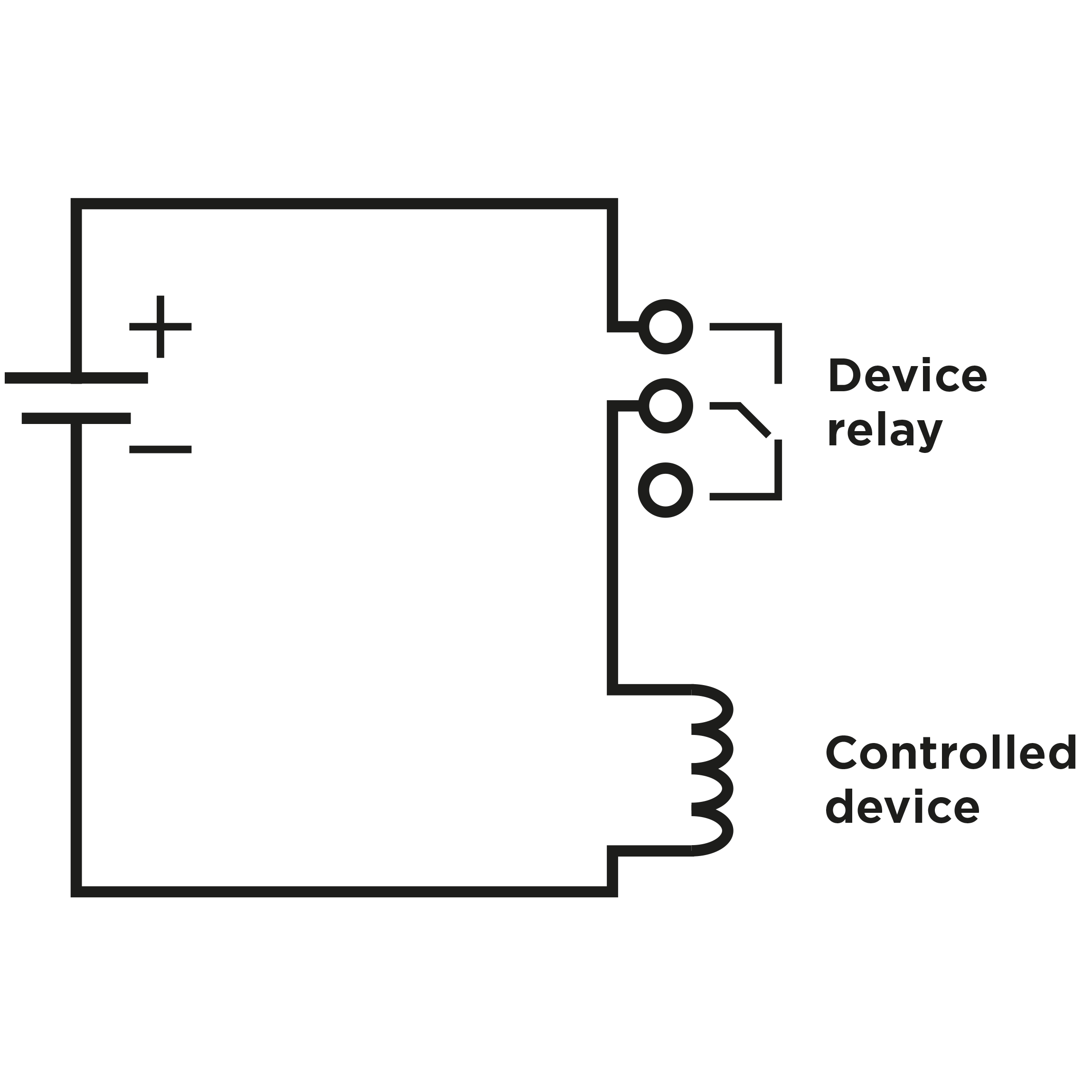 |
Wiring diagram for the controlled device’s electric circuit closing
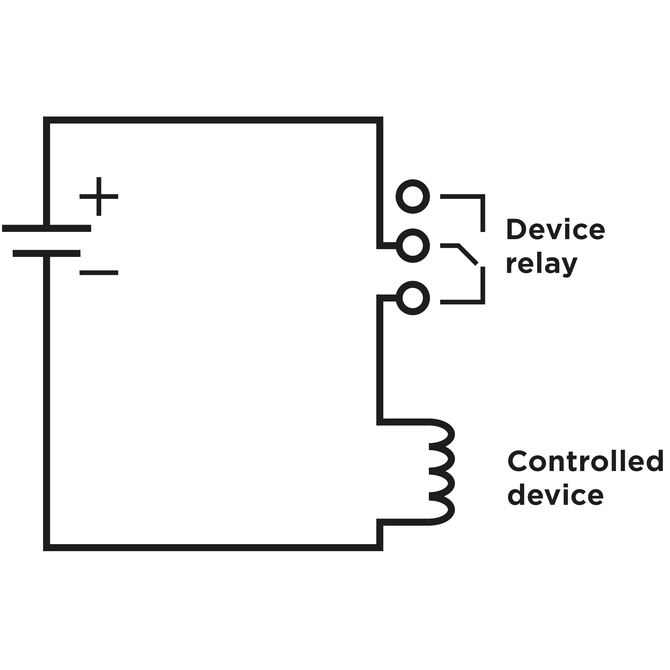 |
Wiring diagram for the controlled device’s electric circuit opening
LAN Connection
2N IP Safety is connected to the LAN via a RJ-45 terminated (connector X11) UTP/STP cable (of category Cat 5e or higher). The system is equipped with the Auto-MDIX function and so both the straight and crossed cable versions can be used.
Caution
- We recommend the use of a LAN surge protection.
- We recommend the use of a shielded SSTP Ethernet cable.
Warning
-
This product cannot be connected directly to the telecommunications lines (or public wireless LANs) of any telecommunication carriers (e.g. mobile communications carriers, fixed communications carriers, or internet providers). In the case of connecting this product to the Internet, be sure to connect it via a router.
External Power Supply Connection
2N IP Safety can be fed either from an external 12 V / 1 A DC power supply or from the LAN equipped with the PoE 802.3af supporting network elements.
Warning
The adapter must provide less than 100 W of power, the LPS/PS2 limit acc. to UL/CSA 60950-1 or UL/CSA 62368-1.
External Power Supply
An external 12 V power supply is connected to terminal block X19. Use a 12 V ±15 % DC power source dimensioned to current intake of 1 A at least (Part No. 91341481E) to ensure a reliable function of your device.
PoE Supply
2N IP Safety is compatible with the PoE 802.3af (Class 0–12.95 W) technology and can be supplied directly from the LAN via compatible network elements. If your LAN in incompatible, insert the PoE injector, Part No. 91758100E, between 2N IP Safety and the nearest network element.
Reset Button
Located among the main unit connectors, the Reset button helps you reset the factory default values, restart the device, find the device IP address and switch the static/dynamic mode.
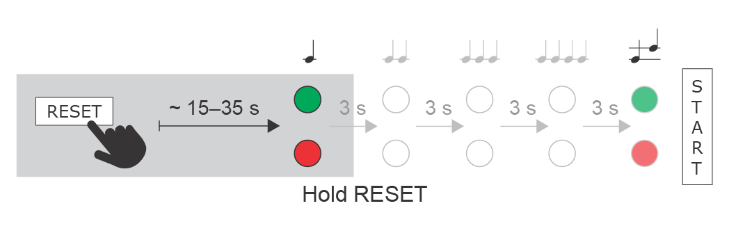
IP Address Finding
Follow the instructions below to identify the current IP address:
- Press and hold the RESET button.
- Wait until the red and green LEDs go on simultaneously on the device and the acoustic signal
 can be heard (approx. 15–35 s).
 - Release the RESET button.
- The device automatically announces the current IP address.
 |
Note
- The delay after pressing RESET till the first light and sound signalling is set to 15–35 s depending on the 2N IP intercom/answering unit model used.
- 24 s is the valid value for 2N IP Safety HW version 8.
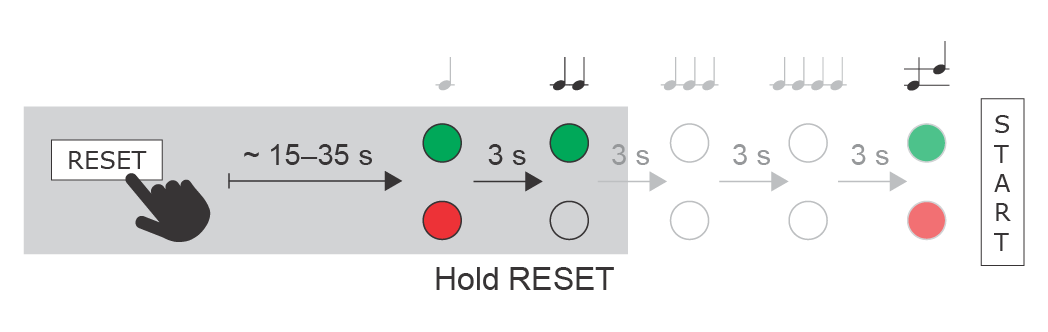
Static IP Address Setting
Follow the instructions below to switch on the Static IP address mode (DHCP OFF):
- Press and hold the RESET button.
- Wait until the red and green LEDs go on simultaneously on the device and the acoustic signal
 can be heard (approx. 15–35 s).
 - Wait until the red LED goes off and the acoustic signal
 can be heard (approx. for another 3 s).
 - Release the RESET button.
The following network parameters will be set after restart:
- IP address: 192.168.1.100
- Network mask: 255.255.255.0
- Default gateway: 192.168.1.1
 |
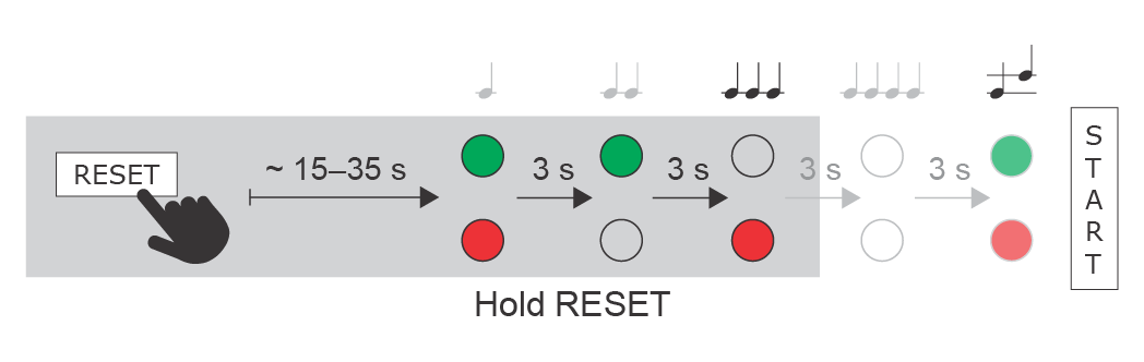
Dynamic IP Address Setting
Follow the instructions below to switch on the Dynamic IP address mode (DCHP ON):
- Press and hold the RESET button.
- Wait until the red and green LEDs go on simultaneously on the device and the acoustic signal can be heard (approx. 15–35 s).
- Wait until the red LED goes off and the acoustic signal can be heard (approx. for another 3 s).
- Wait until the green LED goes off and the red LED goes on again and the acoustic signal
 can be heard (approx. for another 3 s).
 - Release the RESET button.
 |
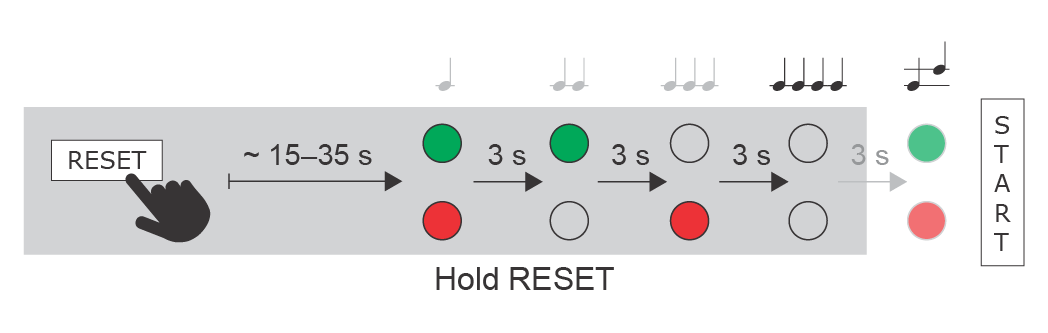
Factory Reset (PCB version 555v4 and higher)
Follow the instructions below to reset the factory default values:
- Press and hold the RESET button.
- Wait until the red and green LEDs go on simultaneously and the acoustic signal can be heard (approx. 15–35 s).
- Wait until the red LED goes off and the acoustic signal can be heard (approx. for another 3 s).
- Wait until the green LED goes off and the red LED goes on again and the acoustic signal can be heard (approx. for another 3 s).
- Wait until the red LED goes off and the acoustic signal
 can be heard (approx. for another 3 s).
 - Release the RESET button.
 |
Caution
- In case of resetting the factory default settings on a device with a version of firmware 2.18 or higher it is necessary to reprogram the
2N Security Relay using the instructions from section 2.4.
Device Restart
Press the RESET button shortly (< 1 s) to restart the system without changing configuration.
Note
- The time interval between the short press of RESET and reconnection after restart is 25–50 s for 2N IP Safety depending on the HW version.
Factory Default Resetting (PCB version 555v3)
For resetting device to default settings press and hold SW1 button. Wait for the sound signalization and then release the button.
Caution
- In case of resetting the factory default settings on a device with a version of firmware 2.18 or higher it is necessary to reprogram the
2N IP Security Relay using the instructions from section 2.4.
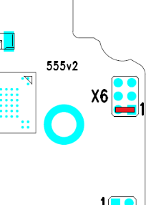
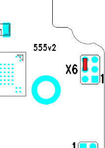
Factory Default Resetting (PCB version 555v2)
- Disconnect the device from the power supply.
- Move the short-circuit jumper on connector X6 into the Default setup position. Configuration jumpers (X6) are located in the right-hand upper corner of the PCB.
- Reconnect the power supply and wait for a start signalling sound.
- Disconnect the device from the power supply.
- Move the short-circuit jumper on connector X6 into the Normal operation position.
- Reconnect the power supply. The device will be reset to factory default.
Configuration jumpers X6, PCB version 555v2:
Normal operation | Default setup |
|
|
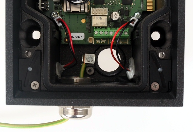
Grounding
We recommend to ground the intercom in order to improve the static electricity resistance. For proper grounding you need a cable of the minimum cross-section of 4 mm2. Connect the cable to the connector in the bottom part of the intercom. The connector is enclosed to the delivery.
|
Mounting Completion
- Having connected all the wires, make sure that the bushings, if used, are tightened properly and the RJ-45 connector is inserted in the PCB connector.
- Replace the front cover carefully. Make sure that the connector is inserted correctly and the wires inside the device leave enough space for the board if you are installing a four-button board. Tighten the four screws thoroughly with the wrench enclosed (Torx 20) to make the panel fit tightly to the metal chassis. Keep the maximum tightening torque of 1.5 Nm.
Caution
- Properly installed intercom is waterproof. An incorrect mounting may compromise the intercom watertightness. Water leakage may damage the electronic part of the system.
- Stainless steel screws are used for the 2N IP Safety assembly. Other screws than stainless steel ones corrode soon and may aesthetically deteriorate the surrounding environment!
Available Switches
| Location | Name | Description |
|---|---|---|
| Basic Unit | Relay 1 | Passive relay switch: NO and NC contacts, up to 30 V / 1 A AC/DC.Used for connection of non-critical devices only (lights, e.g.). |
| Output 1 | Active switch output: 8 up to 12 V DC depending on power supply (PoE: 10 V; adaptor: power supply voltage minus 2 V), max 600 mA | |
Additional Switch (Part No. 9151010) | Relay 2 | Passive relay switch: NO and NC contacts, up to 30 V / 1 A AC/DC. Used for connection of non-critical devices only (lights, e.g.). |
| Output 2 | Active switch output : 8 up to 12 V DC depending on power supply (PoE: 10 V; adaptor: power supply voltage minus 2 V), max 600 mA. |
Warning
When you connect a device containing a coil, such as a relay or an electromagnetic lock, it is necessary to protect the intercom against voltage peak while switching off the induction load. For this way of protection we recommend a diode 1 A / 1000 V (e.g., 1N4007, 1N5407, 1N5408) connected antiparallel to the device.
|
