2.3 Electric Installation
This subsection describes how to install the modules, how to connect the 2N IP Solo main unit to the power supply and LAN and how to connect other elements.
Caution
- The device must be part of the electrical system of the building.
This device must be deployed within a network infrastructure that provides adequate protection against Denial-of-Service (DoS) attacks and similar network-based threats. The device does not include built-in protection against high-volume or malicious traffic and relies on the surrounding network environment—such as firewalls, intrusion prevention systems, or rate limiting—for defense. Failure to implement appropriate network security measures may lead to service degradation or unavailability. The equipment’s user documentation shall contain a description of all exposed network interfaces and all services exposed via network interfaces, which are delivered as part of the factory default state.
Mounting Preparation
- Place the 2N IP Solo on the flush mounting box / pre-drilled holes with dowels and pull the cables through the bottom holes. Pull the Ethernet cable through the bottom hole to the left if necessary.
- Insert the metal fitting elements up and down and screw the access unit tight. You can level the unit slightly in this mounting type.
Main Unit
Power Supply Connection
2N IP Solo can be powered either from an external 12 V / 2 A DC source or directly from the LAN equipped with PoE 802.3af supporting network elements.
Caution
- The external power supply should meet the PS2/LPS power supply class requirements.
External power supply
Use a 12 V ±15 % SELV supply dimensioned to the minimum current consumption of 2 A (Part No. 91341481E) to make your system work reliably.
PoE Power Supply
2N IP Solo is compatible with the PoE 802.3af (Class 0–12,95 W) technology and can be fed directly from the LAN via the compatible network elements. If your LAN does not support this technology, insert a PoE injector, Part No. 91378100, between 2N IP Solo and the nearest network element.
Varování
- 2N IP Solo cannot be fed from an external power supply and PoE at the same time. A combined supply might result in a device damage.
LAN Connection
2N IP Solo is connected to the Local Area Network (LAN) via the UTP/STP cable (Cat 5e or higher) terminated with an RJ-45 (LAN) connector. As the device is equipped with the Auto-MDIX function, both the straight and crossed cable can be used.
Caution
- We recommend the use of a LAN surge protection.
- We recommend the use of a shielded SSTP Ethernet cable with a shielded RJ-45 connector connected to the switch (with the grounding option) via the same shielded connector. This makes the device perfectly grounded.
Basic Unit with Camera (HW version 3) | Basic Unit without Camera (HW version 3) | |||
|---|---|---|---|---|
| 12 V | mA | W | mA | W |
| At relax | 200 | 2.4 | 200 | 1.8 |
| Infrared illumination | 158 | 1.9 | – | – |
| LED – call | 7 | 0.08 | 7 | 0.8 |
| LED – ringing | 5 | 0.06 | 5 | 0.06 |
| LED – lock | 4 | 0.048 | 4 | 0.048 |
| LED – allowed access | 5 | 0.048 | 5 | 0.048 |
| Button backlight | 4 | 0.048 | 4 | 0.048 |
| Name tag backlight | 4 | 0.048 | 4 | 0.048 |
| Unit backlight | 14 | 0.168 | 14 | 0.168 |
| Relay 1 | 16 | 0.2 | 16 | 0.2 |
| OUT 1 | 400 | 4.8 | 400 | 4.8 |
| Audio | 213 | 2.556 *power output of 2 W / 4 ohm | 213 | 2.556 *power output of 2 W / 4 ohm |
| Total | 1.030 [A] | 12.368 [W] | 872 [A] | 10.464 [W] |
Main Unit Connector Configuration
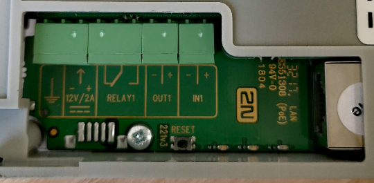 |
| Legend | |
LAN (PoE) | LAN (PoE according to 802.1af) connector |
IN1 | IN1 terminals for input in passive/ active mode (−30 V to +30 V DC) OFF = open OR UIN > 1.5 V ON = closed contact OR UIN < 1.5 V |
OUT1 | OUT1 terminals of active input for 2N Security Relay or electric lock connection 8 up to 12 V DC depending on power supply (PoE: 10 V; adaptor: power supply voltage minus 2 V), max. 600 mA |
RELAY1 | RELAY1 terminals with accessible 30 V / 1 A AC/DC NO/NC contact. Used for connection of non-critical devices only (lights, e.g.). |
12V/2A | External 12 V / 2 A DC supply terminals |
GND | Grounding terminal |
RESET | RESET / FACTORY RESET button |
The device is equipped with a Tamper Switch detecting any unauthorized access to the device. The switch detects any removal of the device from the box. Once the device is removed, software activation is performed as set in the software configuration interface. The device is not equipped with terminals for connection of an external TAMPER reading device.
Tip
- Output wiring diagram for Relay terminals
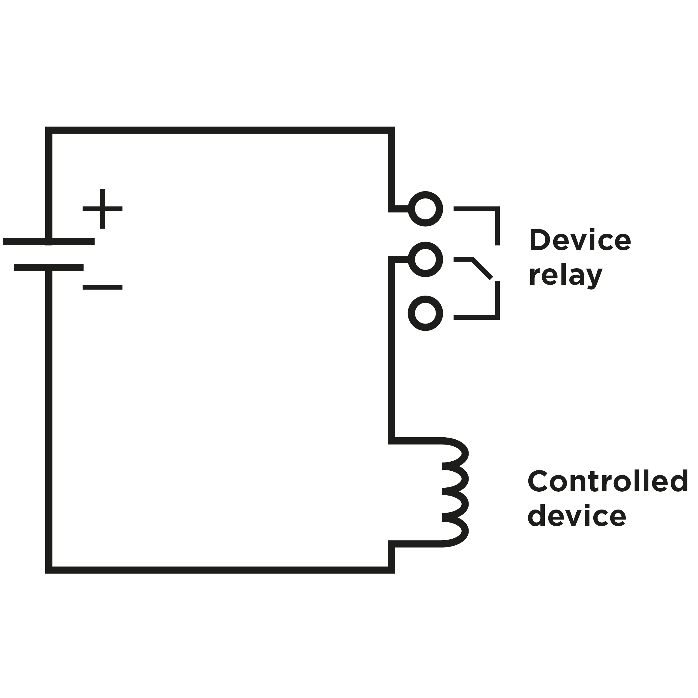 |
Wiring diagram for the controlled device’s electric circuit closing
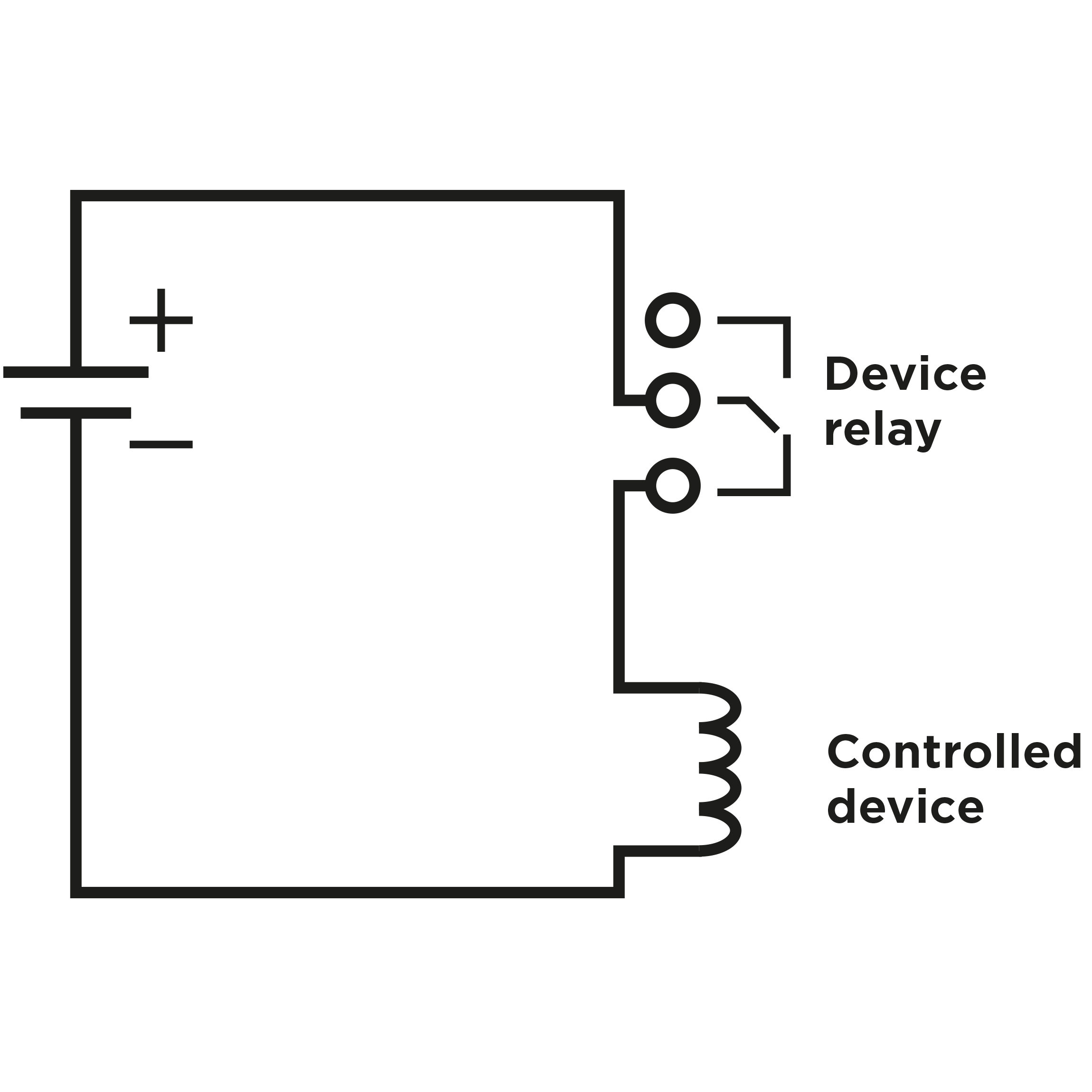 |
Wiring diagram for the controlled device’s electric circuit opening
Tip
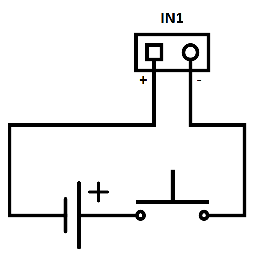
- Wiring Diagram of IN1 connector in active mode
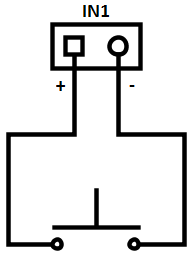 |
- Wiring Diagram of IN1 connector in passive mode
 |
Reset Button
Located among the main unit connectors, the Reset button helps you reset the factory default values, restart the device, find the device IP address and switch the static/dynamic mode.
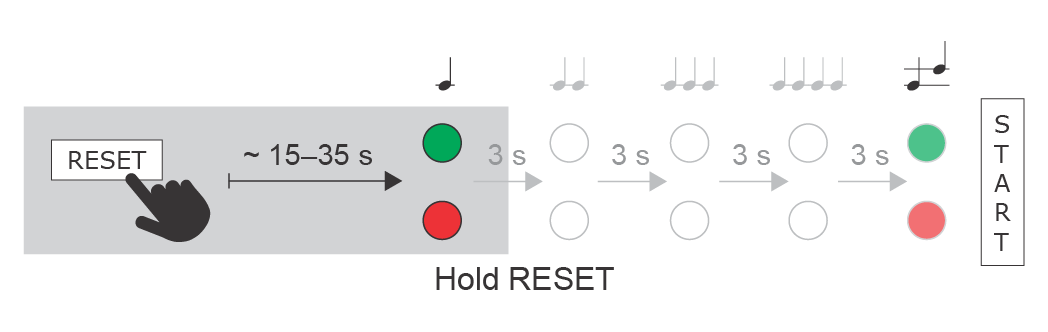
IP Address Finding
Follow the instructions below to identify the current IP address:
- Press and hold the RESET button.
- Wait until the red and green LEDs go on simultaneously on the device and the acoustic signal
 can be heard (approx. 15–35 s).
 - Release the RESET button.
- The device automatically announces the current IP address.
 |
Note
- The delay after pressing RESET till the first light and sound signalling is set to 15–35 s depending on the 2N IP intercom/answering unit model used.
- 18 s is the valid value for 2N IP Solo.
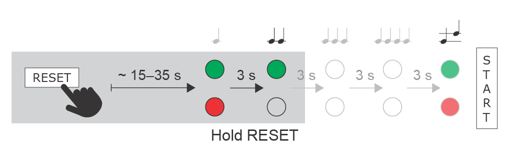
Static IP Address Setting
Follow the instructions below to switch on the Static IP address mode (DHCP OFF):
- Press and hold the RESET button.
- Wait until the red and green LEDs go on simultaneously on the device and the acoustic signal
 can be heard (approx. 15–35 s).
 - Wait until the red LED goes off and the acoustic signal
 can be heard (approx. for another 3 s).
 - Release the RESET button.
The following network parameters will be set after restart:
- IP address: 192.168.1.100
- Network mask: 255.255.255.0
- Default gateway: 192.168.1.1
 |
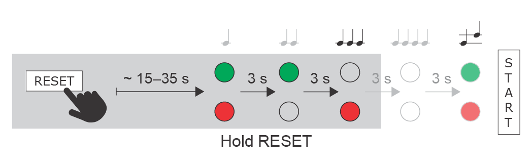
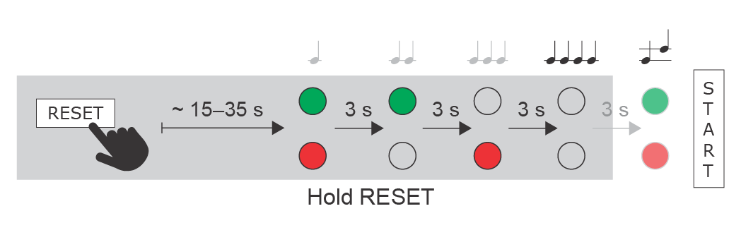
Dynamic IP Address Setting
Follow the instructions below to switch on the Dynamic IP address mode (DCHP ON):
- Press and hold the RESET button.
- Wait until the red and green LEDs go on simultaneously on the device and the acoustic signal can be heard (approx. 15–35 s).
- Wait until the red LED goes off and the acoustic signal can be heard (approx. for another 3 s).
- Wait until the green LED goes off and the red LED goes on again and the acoustic signal
 can be heard (approx. for another 3 s).
 - Release the RESET button.
 |
Factory Reset
Follow the instructions below to reset the factory default values:
- Press and hold the RESET button.
- Wait until the red and green LEDs go on simultaneously and the acoustic signal can be heard (approx. 15–35 s).
- Wait until the red LED goes off and the acoustic signal can be heard (approx. for another 3 s).
- Wait until the green LED goes off and the red LED goes on again and the acoustic signal can be heard (approx. for another 3 s).
- Wait until the red LED goes off and the acoustic signal
 can be heard (approx. for another 3 s).
 - Release the RESET button.
 |
Caution
- In case of resetting the factory default settings on a device with a version of firmware 2.18 or higher it is necessary to reprogram the
2N Security Relay using the instructions from section 2.4.
Device Restart
Press the RESET button shortly (< 1 s) to restart the system without changing configuration.
Note
- The time interval between the short press of RESET and reconnection after restart is 26 s for 2N IP Solo.
Available Outputs
| Location | Name | Description |
|---|---|---|
| Main Unit | Relay 1 | Passive switch: NO/NC contact, up to 30 V / 1 A AC/DC. Used for connection of non-critical devices only (lights, e.g.). |
| Output 1 | Active switch output: 8 up to 12 V DC depending on power supply (PoE: 10 V; adaptor: power supply voltage minus 2 V), max. 600 mA |
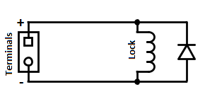
Warning
When you connect a device containing a coil, such as a relay or an electromagnetic lock, it is necessary to protect the intercom against voltage peak while switching off the induction load. For this way of protection we recommend a diode 1 A / 1000 V (e.g., 1N4007, 1N5407, 1N5408) connected antiparallel to the device.
 |
Main Unit LED Pictograms
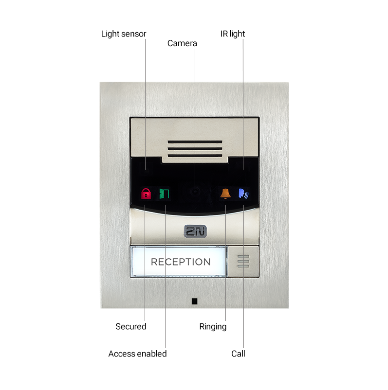 |
Main Unit LED Pictogram Layout