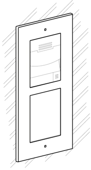
2.2 Mechanical Installation
Mounting Types Overview
Refer to the table below for a list of mounting types and necessary components. You can assemble multiple units in all mounting types.
Flush mounting – classic bricks
- incl. hollow bricks, thermally insulated walls, etc.
What you need for mounting:
- a properly cut hole as instructed in the box package
- Plaster, mounting glue, mounting foam or mortar as necessary
- 2N® IP Verso, flush mounting boxes and frames
- 1 module: box Part No. 9155014, frame Part No. 9155011
- 2 modules: box Part No. 9155015, frame Part No. 9155012
- 3 modules: box Part No. 9155016, frame Part No. 9155013
Flush mounting – plasterboard
What you need for mounting:
- a properly cut hole as instructed in the box package
- 2N® IP Verso, flush mounting boxes and frames
- 1 module: box Part No. 9155014, frame Part No. 9155011
- 2 modules: box Part No. 9155015, frame Part No. 9155012
- 3 modules: box Part No. 9155016, frame Part No. 9155013
 |
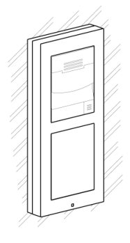
Surface mounting
- concrete and steel structures, entry barrier columns, interior, etc.
What you need for mounting:
- 2N® IP Verso plus the respective frames
- 1 module: frame Part No. 9155021
- 2 modules: frame Part No. 9155022
- 3 modules: frame Part No. 9155023
Backplates (Part Nos. 9155061–9155067) are required for metal, glass and plasterboard surfaces as well as other uneven surfaces depending on the count of modules.
 |
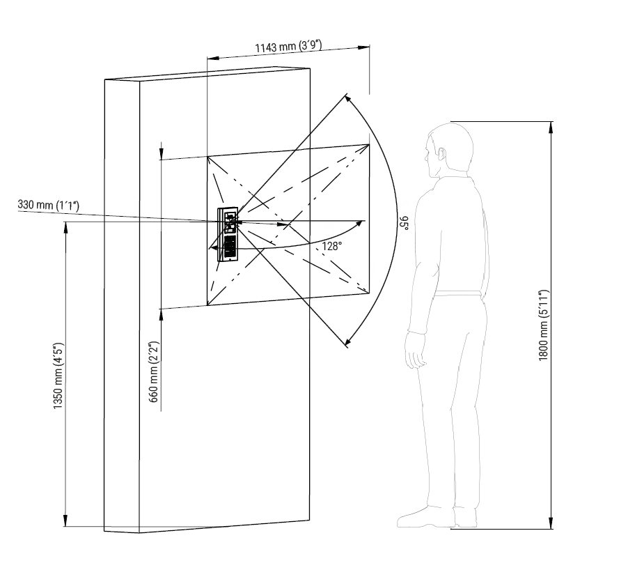
The recommended standard installation height is 1350 mm from the ground to the device camera level. The installation height may vary depending on the device use.
Caution
Before starting the mechanical installation on a selected place, make sure carefully that the preparations connected with it (drilling, wall cutting) cannot damage the electrical, gas, water and other existing wires and pipes.
- The warranty does not apply to the product defects and failures arisen as a result of improper mounting (in contradiction herewith). The manufacturer is neither liable for damage caused by theft within an area that is accessible after the attached electric lock is switched. The product is not designed as a burglar protection device except when used in combination with a standard lock, which has the security function.
- When the proper mounting instructions are not met, water might get in and destroy the electronics. It is because the communicator circuits are under continuous voltage and water infiltration causes an electro-chemical reaction. The manufacturer’s warranty shall be void for products damaged in this way!
- Do not remove the plastic film on the seal inside the frame, otherwise water may leak and damage the electronic components.
General Mounting Principles
Tip
- Select flush mounting where possible to make your product elegant looking, more vandal resistant and more secure.
- You are advised to buy the flush mounting boxes in advance and commission your building company to do the masonry for you. This approach helps you put your intercom exactly in the vertical position.
Caution
- Make sure that the diameter of the dowel holes is accurate to avoid falling out of the dowels! Use the mounting glue to secure the dowels if necessary.
Make sure that the depth of the dowel holes is accurate!
Do not use low-quality dowels to avoid their pulling out of the wall!
Having removed the front panel, make sure that no dirt gets inside the product (especially onto the sealing surface).
- Never turn 2N® IP Verso to align the box assembly after mounting. Make sure that the flush mounting boxes have been installed accurately.
- Check the plasterboard wall and room interior pressure values. If the difference between the values is too great (as a result, e.g., of overpressure ventilation), separate the intercom using, for example, the mounting box enclosed and seal the cable passage to avoid speaker damage.
- Surface mounting may cause problems on places exposed to potential vandalism (such as public garages, etc.). In this case, use steel anchoring elements instead of the dowels and screws included in the delivery.
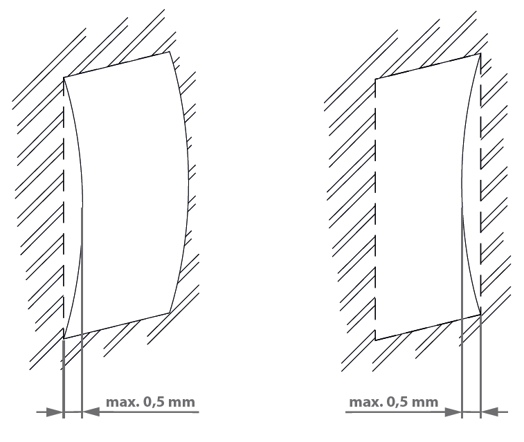
- Make sure that the installation surface is perfectly flat with the maximum inequality of 0.5 mm. (e.g. boards, glass, cut stone, etc). If this is not the case, use a mounting backplate Part No 9155061–9155067, or level the wall surface.
- Always use an installation backplate for uneven installation surfaces.
- While flush mounting, make sure that the box is installed properly, i.e. with the box frame on the wall surface. There are snap-off protrusions on both sides of the flush mounting box to facilitate positioning. Make sure that the frame is placed precisely onto the flush mounting box off the wall to provide effective sealing and avoid water penetration into the intercom. Refer to the pictorial instructions inside the flush mounting box package.
- Any intentional mechanical damage (drilling, main unit tampering, etc.) results in a loss of warranty.
Warning!
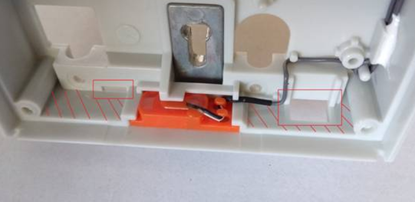 |
- It is forbidden to use silicone or any other sealing material on the marked and hatched places.
Safety
|
- Eliminate the risk of personal injury! Surface mounting is not recommended for narrow passages or places where people's attention is distracted by something else. The manufacturer shall not be liable for injuries in such cases!
Warning
 |
- The main unit may not be removed from its base, so do not remove the marked resin-cast screw in the right-hand upper corner. Any screw tampering results in a loss of warranty.
Module Installation
- 2.2.1 One Module Box
- 2.2.2 Two Modules Box
- 2.2.3 More Two Module Boxes
- 2.2.4 Three Modules Boxes
- 2.2.5 More Three Modules Boxes
- 2.2.6 Tamper and I/O Modules
- 2.2.7 Module Dimensions