2.3 Electric Installation
This subsection describes how to connect the 2N® IP Verso 2.0 main unit to the power supply and LAN and how to connect other elements.
Caution
- The device must be part of the electrical system of the building.
Main Unit
Power Supply Connection
2N® IP Verso 2.0 can be powered either from an external 12 V / 2 A DC source or directly from the LAN equipped with PoE 802.3af supporting network elements. Owing to different power outputs, the power supply selection affects the maximum count and applicability of the modules connected of the main unit.
Caution
- The external power supply should meet the PS2/LPS power supply class requirements.
External power supply
For reliability reasons, use a 12 V ±15% SELV supply dimensioned to the current consumption as required for feeding of the main unit and connected extending modules.
Current consumption [A] | Part number | Avaible power output [W] |
|---|---|---|
| 2 | 91341481E | 24 |
| 3 | 36 |
PoE Power Supply
2N® IP Verso 2.0 is compatible with the PoE 802.3af (Class 0–12,95 W) technology and can be fed directly from the LAN via the compatible network elements. If your LAN does not support this technology, insert a PoE injector, Part No. 91378100, between 2N® IP Verso 2.0 and the nearest network element. This power supply provides 2N® IP Verso 2.0 with 12 W for feeding of the main unit and connected modules.
Combined Power Supply
2N® IP Verso 2.0 can be fed from an external power supply and PoE at the same time. In this configuration, the maximum power for the connected modules is available.
LAN Connection
2N® IP Verso 2.0 is connected to the Local Area Network (LAN) via the UTP/STP cable (Cat 5e or higher) terminated with an RJ-45 (LAN) connector. As the device is equipped with the Auto-MDIX function, both the straight and crossed cable can be used.
Caution
- We recommend the use of a LAN surge protection.
- We recommend the use of a shielded SSTP Ethernet cable with a shielded RJ-45 connector connected to the switch (with the grounding option) via the same shielded connector. This makes the device perfectly grounded.
Tip
- Remove the connector protecting cover to pass through the UTP/STP cable RJ terminal to the device box more easily.
Warning
-
This product cannot be connected directly to the telecommunications lines (or public wireless LANs) of any telecommunication carriers (e.g. mobile communications carriers, fixed communications carriers, or internet providers). In the case of connecting this product to the Internet, be sure to connect it via a router.
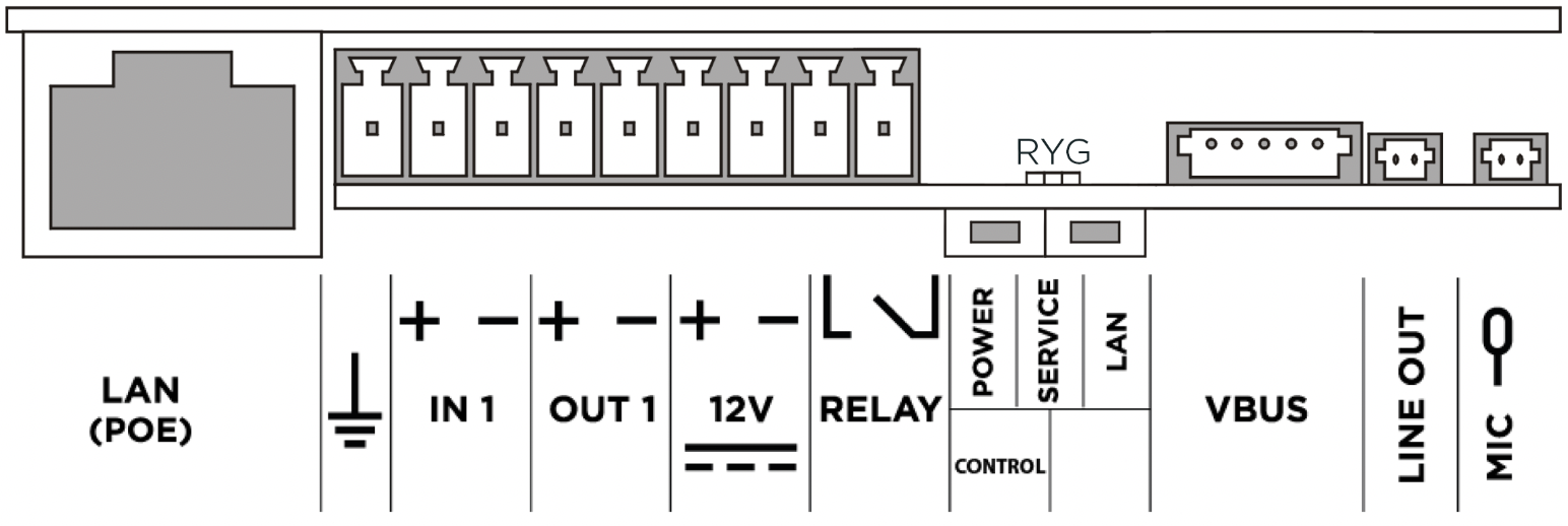
Main Unit Connector Configuration
|
| Legend | |
LAN (PoE) | LAN (PoE according to 802.3af) connector |
GND | Grounding terminal |
IN1 | IN1 terminals for input in passive/ active mode (−30 V to +30 V DC)
|
OUT1 | OUT1 terminals of active input for 2N® Security Relay or electric lock connection 8 up to 12 V DC depending on power supply (PoE: 10 V; adaptor: power supply voltage minus 2 V), max. 600 mA |
12 V / 2 A | External 12 V / 2 A DC supply terminals |
RELAY | RELAY terminals with accessible 30 V / 1 A AC/DC NO contact. |
POWER/SERVICE/LAN | LED indicators (red/green/yellow) |
CONTROL | Button for resetting the device to factory settings |
BOOT | The button is used for advanced diagnostic hardware operations, but does not respond to a common user’s press. |
VBUS | VBUS connector |
LINE OUT | LINE OUT connector (1 VRMS). Connector type JST SHR-02V-S. |
MIC | MIC connector for microphone connection |
Caution
- We recommend that a grounding cable of the cross-section of 1.5 mm2 is used.
Tip
Relay output wiring diagram
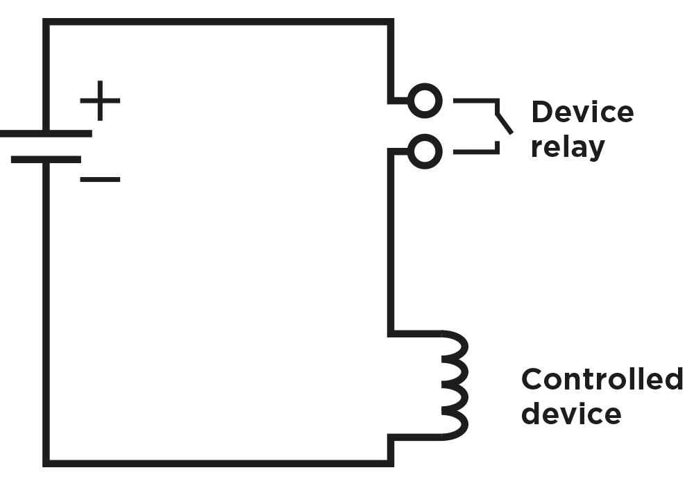
Wiring diagram for making of the electric circuit of the device to be controlled
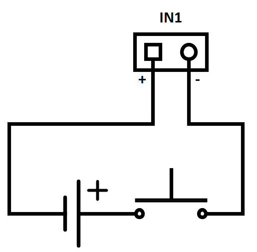
Tip
- Wiring Diagram of IN1 connector in active mode
- Wiring Diagram of IN1 connector in passive mode
 |
Available Switches
| Location | Name | Description |
|---|---|---|
| Main Unit | RELAY | Passive switch: make contact, up to 30 V / 1 A AC/DC |
| OUT | Active switch output: 8 to 12 V DC according to power supply (PoE: 10 V; adapter: source voltage minus 2 V), up to 600 mA | |
I/O* Module (Part No. 9155034) | ext.relay1 | Passive switch: make and break contact, up to 30 V / 1 A AC/DC Used for connection of non-critical devices only (lights, e.g.). |
| ext.relay2 | Passive switch: make and break contact, up to 30 V / 1 A AC/DC Used for connection of non-critical devices only (lights, e.g.). |
You can use any number of the modules marked with *.
Security
- The 12V output is used for lock connection. If, however, the unit (2N IP Intercom, 2N Access Unit) is installed where unauthorized tampering may happen (building envelopes), we strongly recommend that 2N® Security Relay (Part No. 9159010) be used for enhanced installation security.
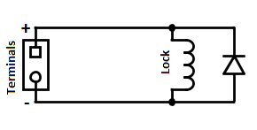
Warning
If a coil containing device is connected, e.g. a relay / electromagnetic lock, it is necessary to protect the intercom output against voltage peak while switching off the induction load. For this way of protection, we recommend a 1 A / 1000 V diode (e.g., 1N4007, 1N5407, 1N5408) connected antiparallel to the device.
 |
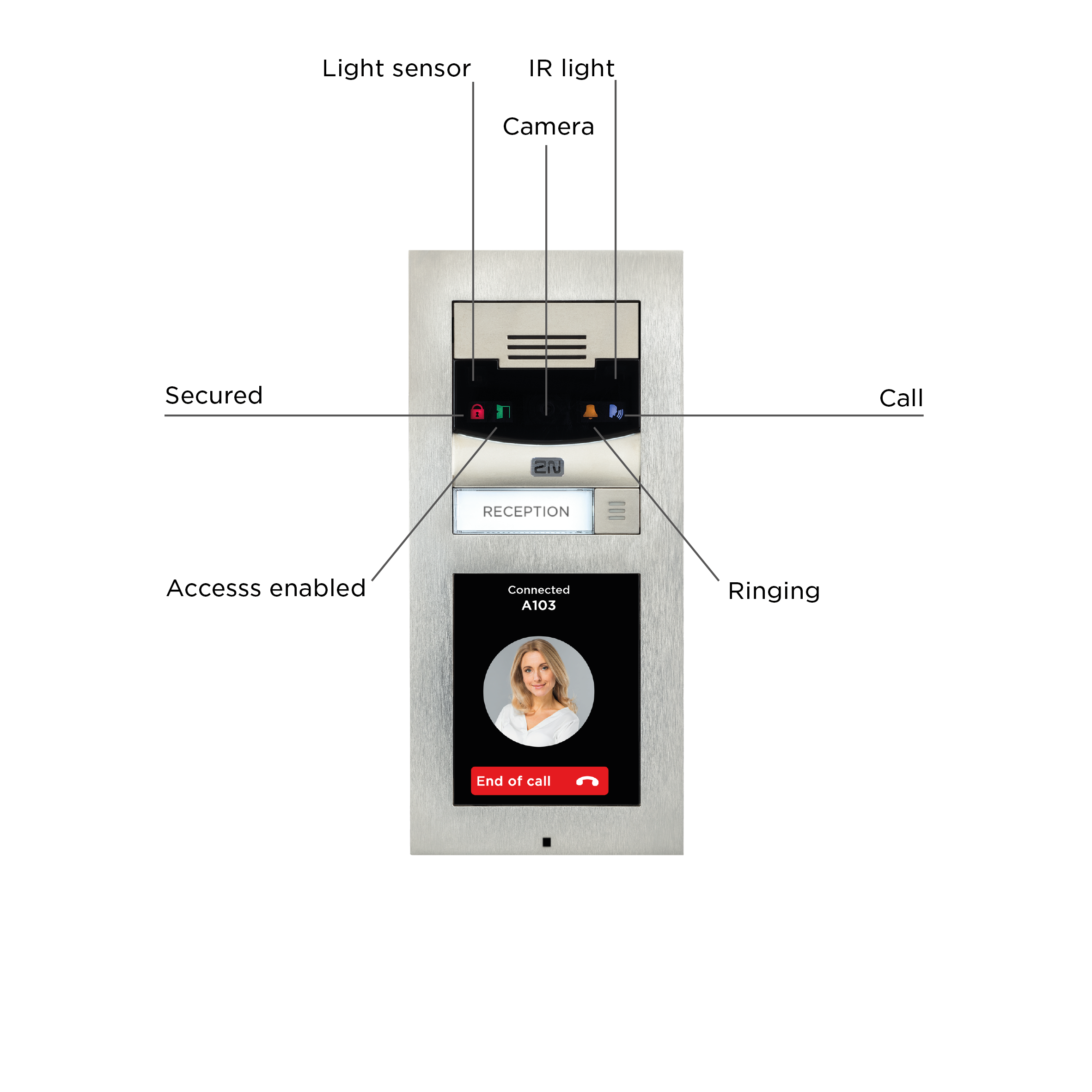
Main Unit LED Pictograms
 |