2.3 Mounting – Universal Design
Safety Precautions
Safety
- The telephone line, microphone, speaker, LED indicators, ALARM button, CANCEL input, cables and electronics are connected with the telephone line. Therefore, make sure that the product installation prevents any contact between the user and these parts to avoid electrical accident. Keep the isolation distance of 1.5 mm at least or insulation breakdown voltage of 1500 V at least!
Caution
- Make sure that the position, appearance and marking of the communicator controls (ALARM button, e.g.) are in accordance with the applicable lift standards.
2N® Lift1 Position
2N® Lift1can be mounted in any position as required. The optimum position
for 2N® Lift1 is approximately on the level of an adult's mouth.
Install 2N® Lift1 on a place where any contact of the operating personnel with the device is eliminated (refer to Safety Precautions).
Caution
- Installing electronics without the mounting panel is not recommended as the panel is used as electric insulation and the manufacturer cannot guarantee safety if the panel is not used.
2N® Lift1 Electronics Panel Mounting
What you need to mount the electronics panel onto the lift button panel (from inside): four 57×122 mm spot-welded M4 screws and sufficiently perforated speaker area (may be larger than as shown in the figure but may never exceed the panel size to avoid acoustic fault), microphone hole and two LED holes if necessary.
Mounting Drawing for 50 mm Speaker Installation
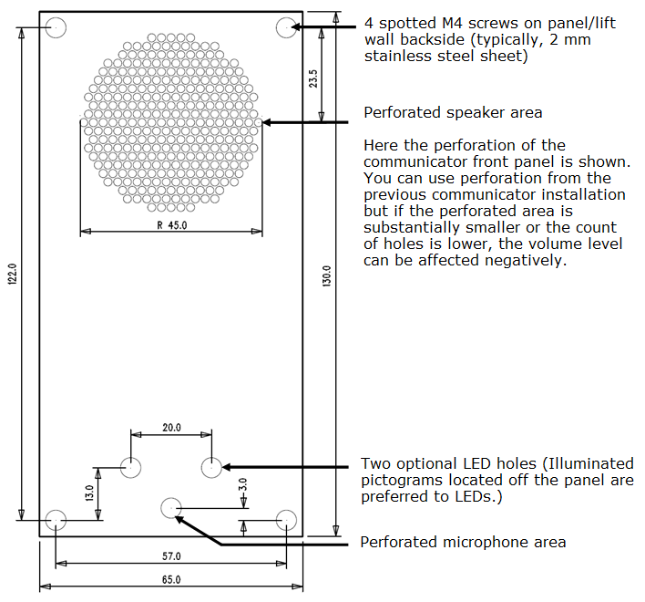 |
If you use other than the prescribed screws, make sure that the isolation distance between the electronics and substandard fitting elements is 2 mm at least. Make sure that the panel is fitted perfectly to avoid resonance during operation. There may be no gap between the lift button panel and 2N® Lift1 or the gap must be sealed properly to eliminate acoustic fault of the speaker and acoustic feedback between the speaker and microphone (see below).
Caution
- Make sure that microphone hole is sealed properly to record only sounds from the cabin instead of the noise from the shaft or space behind the panel.
Off-Panel Microphone Mounting
By default, the microphone is mounted directly on the printed circuit (see the drawing for its position). If required, the microphone can be supplied with a cable mounted on a 25 x 25 mm holder with self-adhesive foil. This allows you to mount the microphone behind any lift button panel hole of the minimum diameter of 3 mm or a group of holes of the same total area. The 2N® Lift1 microphone is on the board, but an external microphone can be connected via a connector. Switching to an external microphone is automatic (its connection is detected).
The minimum centre-to-centre distance between the speaker and microphone is 90 mm. A shorter distance may result in acoustic feedback. A longer distance does not matter.
Warning
- Make sure that the microphone hole is sealed properly against the noise from the gap between the lift cabin wall and mounting panel. The microphone should record sounds from the cabin instead of noise from the shaft or space behind the panel!
Off-Panel Speaker Mounting
By default, the speaker is mounted on a panel and equipped with a 1m cable for additional amplifier installation. You can also remove the speaker from its panel bed and place it separately. In that case, respect the electric safety precautions, see below!
Caution
- Installing the speaker separately, make sure that the grid cannot surpass the speaker dimensions in any case to eliminate the acoustic fault between the speaker front and back sides!
Safety
- If the speaker is installed separately, ensure the minimum electric isolation of 1500 V between the panel and speaker.
- Also, make sure that the isolation distance between the panel and speaker is 1.5 mm at least.
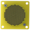
- Mount the 50 mm speaker on an insulating (non-metallic) surface only or require an external panel (not included in the delivery), see the figure below.
 |
Caution
- We do not recommend you to install the microphone and speaker on completely different cabin sites (ceiling and wall, e.g.) to allow the users to find the microphone easily next to the speaker grid/perforation.
Indicator Mounting
There are three types of 2N® Lift1 state indicators:
- Illuminated pictograms are part of the cabin control panel.
- LEDs on the 2N® Lift1 electronics plus optional light guides conducting light to two panel holes.
- Two optional highly luminuous LEDs can be connected to 2N® Lift1 via a cable.
Safety
- If you connect two optional LEDs with a cable, make sure that the electric isolation between the panel and speaker is 1500 V at least.
- Also, make sure that the isolation distance between the panel and speaker is 1.5 mm at least.
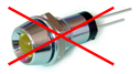
- It is prohibited to use standard metal LED holders, see the figure!
 |
Note
- Make sure that your indicators comply with the applicable legal regulations. However, no indicators are necessary for the 2N® Lift1 communication.