2.5 Installation – Universal Design
Description of Terminals, Connectors and Jumpers
Terminals
 |
Note
- You can access the terminals without removing the cover.
Connectors Accessible after Cover Removal
 |
Tip
- With HW2, the bottom connectors are accessible without the cover being removed.
Description of Terminals and Connectors
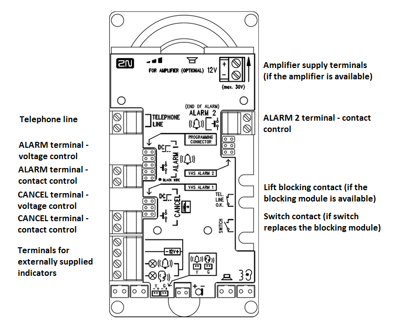
Telephone line | Polarity does not matter. Connect a PSTN, PBX or GSM gateway line directly. CAUTION – Never connect multiple devices to a single line!!! | ||
ALARM terminal | voltage control *) | 6–24 V DC voltage, any polarity | Alarm call activation Activation mode (NO, NC, auto detection) is set by parameter 920. |
contact control | closing/opening contact | ||
CANCEL terminal | voltage control *) | 6–24 V DC voltage, any polarity | Alarm call deactivation CANCEL input inversion is set by parameter 916. |
contact control | closing/opening contact | ||
ALARM 2 connector (button 2) | closing contact | Press button 2 (ALARM2) to set up a call to the numbers in memory 021–026. The activation mode (closing, opening, auto detection) is set in parameter 925. | |
| Indicator terminals *) | Indicators (illuminated pictograms) – 12 V (up to 24V) / 2 x 200 mA, externally supplied, the wiring diagram must be maintained.
| ||
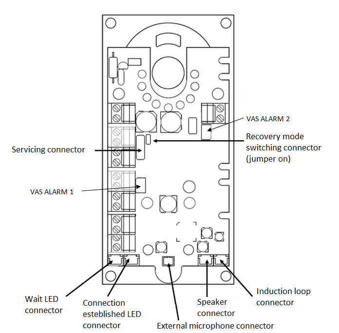
"Wait" LED connector | yellow | LEDs are not part of the delivery by default (except for cable versions). | |
"Connection established" LED connector | green | ||
| VAS ALARM 1 | Connection of Voice ALARM station – the call is set up to a number in memories 011–016 (ALARM 1) | Refer to Subs. 2.8 for details. | |
| VAS ALARM 2 | Connection of Voice ALARM station – the call is set up to a number in memories 021–026 (ALARM 2) | ||
External microphone connector | If an external electret microphone is connected (upon request), the integrated microphone is disconnected automatically. | ||
Speaker connector | The speaker is connected to this connector by default. | ||
Induction loop connector (optional) | The induction loop is not part of the delivery by default. Install the loop behind a non-conductive non-metallic cover. Polarity does not matter.
| ||
Lift blocking contact *) **) | The contact opens whenever a power failure occurs. The lift arrives in the nearest floor and opens the door. The lift will not go on until the line function is recovered.
| ||
Switch 2 contact *) **) | The switches are used for variable purposes and are remotely DTMF-controlled (numeric code). The switches are not designed for 230 V! | ||
Switch 1 contact *) **) | |||
| Button 2 connector | Button 2 is dedicated for a closing contact, it can be used for outgoing call activation or rescue end signalling. | ||
| Service connector | Used for connection of 2N Lift1 to the 2N Lift1 Service Tool via a USB socket changer (refer to Subs. 3.3 for details). | ||
| Recovery mode switching connector | If there is a 2N Lift1 – 2N Lift1 Service Tool connection problem, put the jumper on this connector to switch 2N Lift1 into the recovery mode for firmware upgrade. Connect the button 2 contacts for 5 seconds to reset the factory values. It is equivalent to parameter 999 and can be used if the service password gets lost. (Disconnect 2N Lift1 from the telephone line and put the jumper on the connector to switch on the recovery mode. Now reconnect the telephone line and connect the contact for button 2 for 5 seconds. The green and yellow LEDs start flashing to indicate configuration recovery.) | ||
*) These terminals are safely electrically isolated from the telephone line.
**) Extending module terminals. The blocking module can be mounted if switch 2 is not installed.
2N Lift1 Connection to Telephone Line
2N Lift1 works regardless of polarity and line parameters (refer to Technical Parameters). Connect it using the LINE terminals. A great advantage of 2N Lift1 is that it requires no additional power supply for its function. Refer to 2N Lift1 Connection Methods for PSTN/PBX/GSM connection details.
ALARM 1 Connection – Voltage Control
Tip
- Use 12–24 V DC voltage of any polarity. Make sure that the voltage supply is backed up against power failure.
- Slide the ALARM terminal out and put it in the upper position to ensure the required telephone line isolation.
- Activation can be made by connecting/disconnecting voltage or auto detection upon start. Use parameter 920 for setting.
ALARM 1 Connection – Contact Control
Safety
- Make sure that the ALARM button is safe – keep the isolation distance of 1.5 mm and breakdown voltage of 1500 V at least. Never connect the button contacts to any other circuits. If you cannot meet these conditions, use voltage control.
- Connect the button contacts to the ALARM terminal leaving the terminal in the lower position.
- The button can have a normally open/close contact or auto detection upon start. Use parameter 920 for setting.
Note
For autodetection, connect all the inputs before starting 2N Lift1. The device will be set according to parameter 920 using auto detection.
ALARM 2 (Button 2)
ALARM 2 is used for call setup or rescue end.
Short press (approx. 100 ms) – to set up a call to the numbers stored in memories 021–022 (if empty, memories 011–016 are used).
The button can have a NO / NC contact function or auto detection upon start. Set the function using parameter 925.
Long press (approx. 3 s) – to end the rescue process if the rescue function is enabled (966 = 1,3). The yellow LED goes off (if Lift1 is fed with 12 V).
Note
For autodetection, connect all the inputs before starting 2N Lift1. The device will be set according to parameter 925 using auto detection.
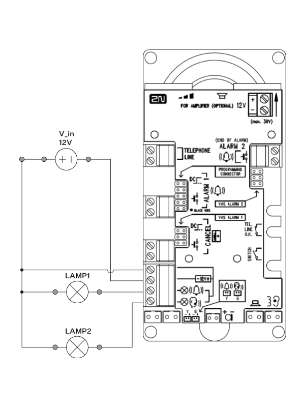
Indicator Connection
Basic Configuration
Use any indicators in this mode (illuminated pictograms/icons, e.g.). An external power supply provides the indicators with a sufficient brightness level. 2N Lift1 contains switches only; current limitation, if required (for LEDs, e.g.), is ensured by a connected circuit. Unlike the LEDs supplied directly from the 2N Lift1 electronics that do not shine during short-time on-hooks between automatically dialled calls (voltage cannot be detected from a hung-up line), the connection request indicator is illuminated during the whole connection setup time when external indicators are used.
 |
Requirements
- 12–24 V power supply (backed up against power outage if required)
- Up to 200 mA continuous current (bulbs can be connected)
- Both the indicators must be connected!
Warning
- Maintain the power supply polarity!
- See the Lift1 cover for the wiring diagram.
2N Lift1 Board Mounted LEDs
Do not connect anything in this case. Use light guides for this purpose to bring light to the two panel holes (refer to 2N Lift1 Electronics Panel Mounting). The light guides are not included in the standard delivery.
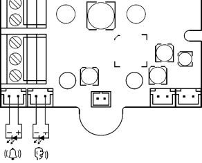
Cable Connected LEDs
Use these LEDs where no illuminated pictograms are available. These LEDs are not included in the standard delivery. Order them separately or within a client solution. They are highly luminous LEDs of the diameter of 5 mm.
 |
Requirements
- Maintain the LED polarity (see the cover printing).
- Keep the colours: request confirmation – yellow, connection confirmation – green.
Note
- The LED on the PCB is not illuminated in this configuration.
CANCEL Connection - Door Contact, Optional
Caution
- The door switch or door opening signal indicates that the door is open only if both the internal and external lift doors are open and people can leave the cabin.
Note
- To use the CANCEL input, program parameter 914 to a timeout longer than the maximum lift running time (i.e. the time during which the door is closed). If parameter 914 is set to 0, it is useless to set the CANCEL input connection.
Contact Control
Safety
- The CANCEL contact input is connected with the telephone line circuits. Therefore, make sure that the air gap between the switch and the other lift parts is 1.5 mm and the breakdown voltage is 1500 V at least. Make sure that the switch contacts are not connected to any other circuits. If these conditions cannot be met, use voltage control.
- Connect the switch to the CANCEL terminal leaving the terminal in the lower position.
- By default, 2N Lift1 is configured for a switch that is closed when the door is open. If the switch is closed when the door is closed, set parameter 916 – refer to Programming).
Voltage Control
Use 12 to 24 V DC voltage of any polarity.
- Slide the CANCEL terminal out and put it in the upper position to ensure the required telephone line isolation.
- By default, 2N Lift1 is configured for a sensor that applies voltage when the door is open. If the sensor applies voltage when the door is closed, set parameter 916 – refer to Programming).
Caution
- If voltage presence signals that the door is closed, make sure that the power supply is backed up against power outage.
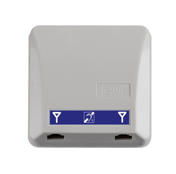
Induction Loop Connection
Mind that the applicable regulations might require cabin installation of an induction loop for deaf people. The loop is connected to the 2N Lift1 back side connector with any polarity or may be part of the delivery if agreed so, including a 4m cable.
|
Requirements
- You are recommended to install the induction loop behind a non-metallic, non-magnetic cover to avoid the loop radiation interference.
- Make sure that the induction loop is marked with a proper symbol (ear) and installed in accordance with the applicable standards.
Extending Module Installation
Extending Module Positions
Connect the module on the Lift1 right-hand side under the ALARM 2 button terminals.
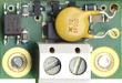
Switch Installation
Install the Universal switch module (Part No. 913648E) before installing your 2N Lift1 without removing the 2N Lift1 cover. Slide the module into the cut-outs on the motherboard edges and tighten the two screws (through the panel holes).
|
Caution
- Make sure that both the screws are tightened properly!
- 2N Lift1 can be equipped with a switch or a lift blocking module (never at the same time).
Warning
- In reality, the "contact" is represented by a semi-conductor with the resistance of approx. 0.5 Ω in the closed mode. Closing at a voltage value lower than 9 V may result in troubles – the switch function cannot be tested using a standard ohmmeter, which only uses small voltage for metering.
- The maximum current to be switched is 1 A. The switch is protected against higher current values with a resettable fuse.
- The allowed voltage is 9 to 24 V DC / AC. The switch is protected against surges with an overvoltage protector.
- The switch "contact" is safely electrically isolated from the telephone line, but is designed exclusively for low-voltage current applications: cannot switch 230 V / 120 V mains voltage.
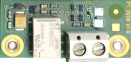
Lift Blocking Module Installation
Install the Lift blocking module (Part No. 913649E) before installing your 2N Lift1 (see the figure above) without removing the 2N Lift1 cover. Slide the module into the cut-outs on the motherboard edges and tighten the two screws (through the panel holes).
|
Caution
- Make sure that both the screws are tightened properly!
- 2N Lift1 can be equipped with a switch or lift blocking module (never at the same time).
Module function
The contact is closed when the telephone line is OK.
Caution
- The module responds to telephone line disconnection with an up to 10-minute delay.
- The maximum current to be switched is 1 A. The maximum allowed voltage is 24 V. It is a mechanical contact (relay).
Warning
- The module contact is safely electrically isolated from the telephone line, but is designed exclusively for low-voltage current applications: cannot switch 230 V / 120 V mains voltage.
Amplifier Installation
Follow the instructions enclosed to the amplifier delivery.