2.8 Voice Alarm Station
Description
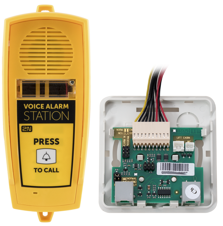
The 2N® Voice Alarm Station extends the 2N® Lift1 with an audio unit installed on the cabin roof and under the cabin. It is an audio panel switch, which interconnects 2N® Lift1 with one or two audio units.
2N® Lift1 – 919640, 919640X
Operation
Use Press to call to activate the device and set up a call to the number set in 2N® Lift1 (with VAS ALARM 1 setting, the call is set up to the ALARM 1 memories 011 to 016, with VAS ALARM 2 setting, the call is set up to the ALARM 2 memories 021 to 026).
Caution
- The audio unit does not contain any call-setup indicating LED. The LED on 2N® Lift1 is illuminated to indicate call setup and confirmation.
- It is necessary to wait for approx. 30 s for call setup from another audio unit. The switch remembers the last alarm-calling audio unit and when alarm is generated from another audio unit within 30 s, the call is set up from the audio unit that was the last to make the alarm call.
Mounting – Universal Design
Disconnect the speaker and microphone from the cables on 2N® Lift1 (external microphone if mounted).
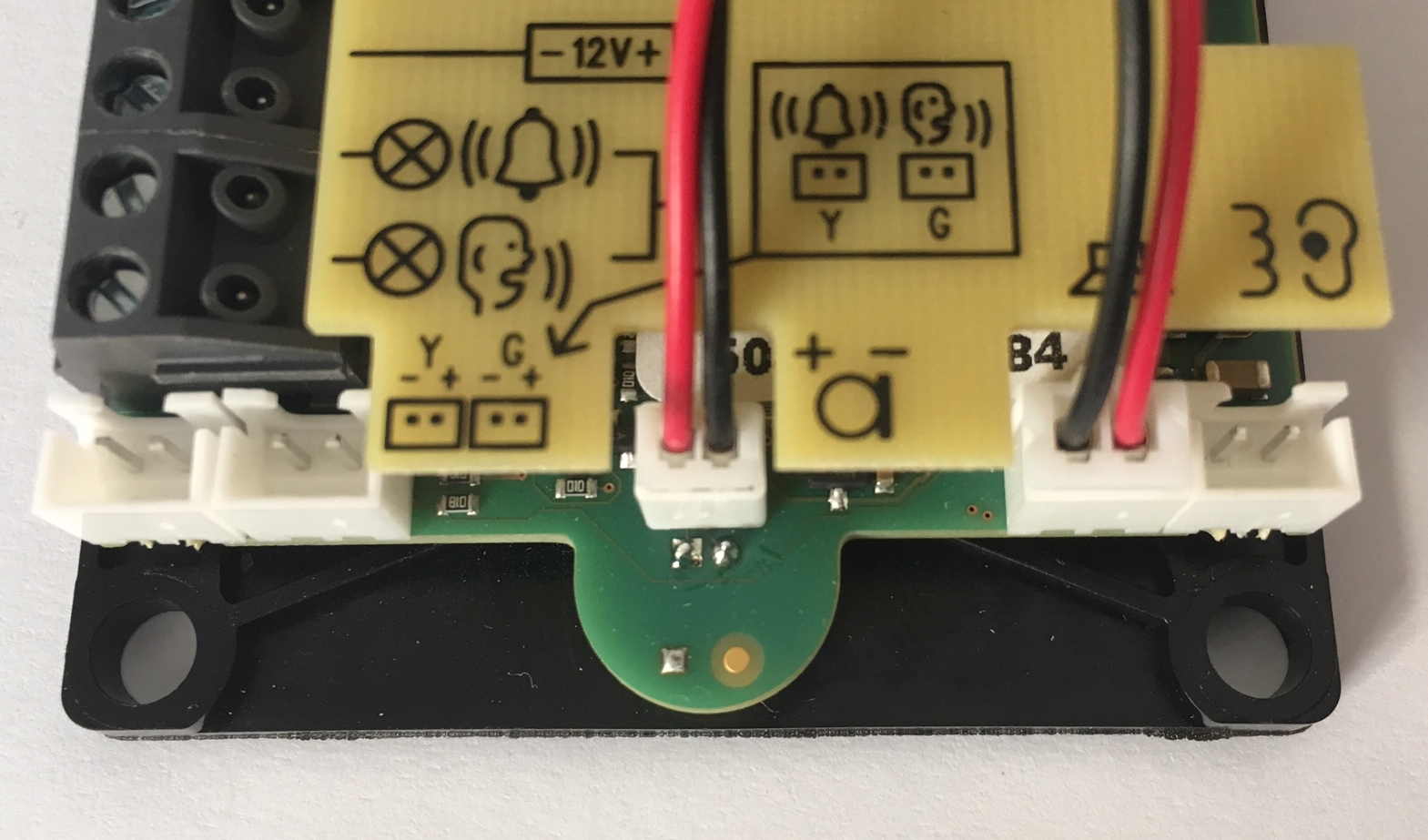
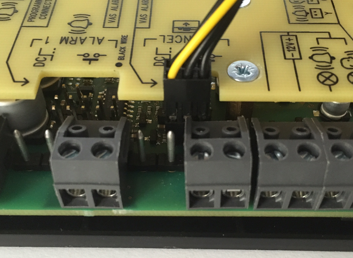
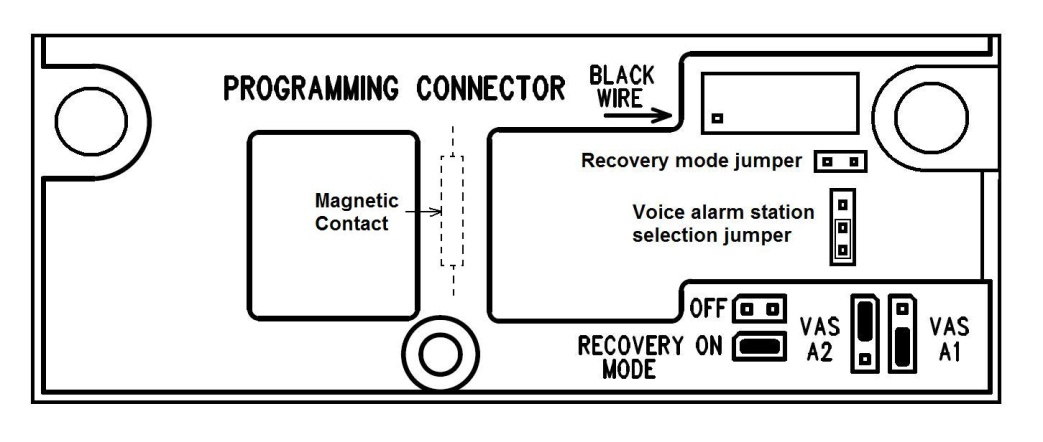
Connect the cable connectors included in the delivery to the 2N® Lift1 microphone and speaker connectors (you cannot confuse the microphone/speaker connectors as they are of different size and there are clear pictograms on the audio unit cover). Put the 6-pin connector on the VAS ALARM 1 or VAS ALARM 2 jumper.
With VAS ALARM 1 connection, calls are set up to the numbers in ALARM 1 memories (011–016); with VAS ALARM 2 connection, calls are set up to the numbers in ALARM 2 memories (021–026).
Microphone and Speaker Connection |
VAS ALARM 1 |
VAS ALARM 2 |
Warning
- Make sure that the 6-pin connection is correct to avoid product damage.
- Make sure that the yellow wire is up (when viewing the audio unit).
Remove the cover from the switch. Interconnect the switch and the 2N® Lift1 audio unit with the cable included in the delivery.
Connect the microphone and speaker from 2N® Lift1 in the point-switch. The speaker and microphone connectors are marked (SPK and MIC). Pull the cables through the holes.
Caution
- In the case of a cable version of 2N® Lift1, an external microphone should be connected into the microphone input on the cable-switch. If you do not have a cable version, this input should be free.
Break out cable holes in the switch upper cover. Then replace the cover. There are 2 RJ12 connectors on the point-switch side for audio unit connection. Interconnect the audio unit and the switch using the cable supplied.
Mounting – Compact
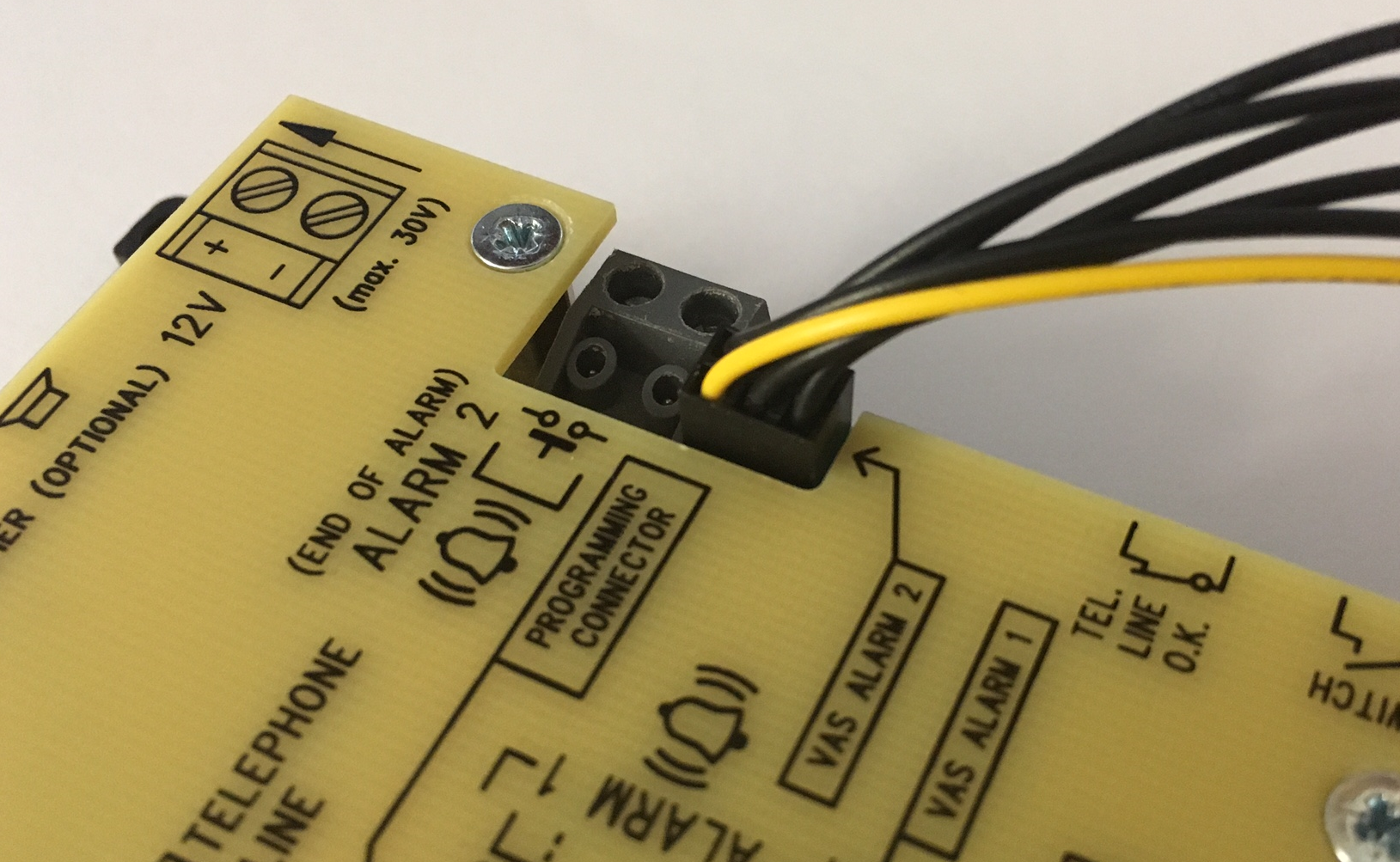
The Voice Alarm station connector is located on the 2N® Lift1 Compact back side. Pull out the 14-pin jumper from the connector and replace it with the connector of the cable enclosed. Connect the 14-pin connector as shown in the back cover diagram (see the figure below).
Warning
- Make sure that the 14-pin connection is correct to avoid product damage.
- Connect the connector as shown in the figure below. Make sure that the dot on the connector is up in the connection (when looking at the 2N® Lift1 Compact back side).
Remove the cover from the switch. Interconnect the switch and the 2N® Lift1 Compact audio unit with the cable included in the delivery. Connect the 10-pin, microphone and speaker connectors in the switch (each of them has a different size and cannot thus be interchanged). The speaker and microphone connectors are marked SPK and MIC. Pull the enclosed cables through the holes.
Break out cable holes in the switch upper cover. Then replace the cover. There are 2 RJ12 connectors on the point-switch side for audio unit connection. Interconnect the audio unit and the switch using the cable supplied.
2N® Lift1 Compact is configured to make calls to memories 011–016 (VAS ALARM 1) by default. To direct calls to memories 021–026 (VAS ALARM 2), shift the jumper under the glass.
Dimensions
Audio unit – Voice alarm station: 225 x 87 x 67 mm
Audio panel switch: 81 x 81 x 30 mm

