2.2 Splitter
The 2N Lift8 splitter helps extend installations where the connection of the audio units to the Central Unit is insufficient. It is suitable for cases where it is necessary to connect more than one elevator shaft or more than 8 audio units/floors in the Evacuation mode.
The splitter also contains a make/break contact for the lift blocking function. There can be up to 7 splitters (according to the count of lift shafts).
Each splitter must be configured for a different address (lift shaft number) for the system to work. The address is set as 2-8 (shaft 2-8). Address 1 is reserved for the Central Unit
The splitters are connected in series, i.e. one after another (never in parallel), to avoid system instability. The termination resistance (jumper) is mounted on the last splitter or IO module (furthest from the CU).
Description
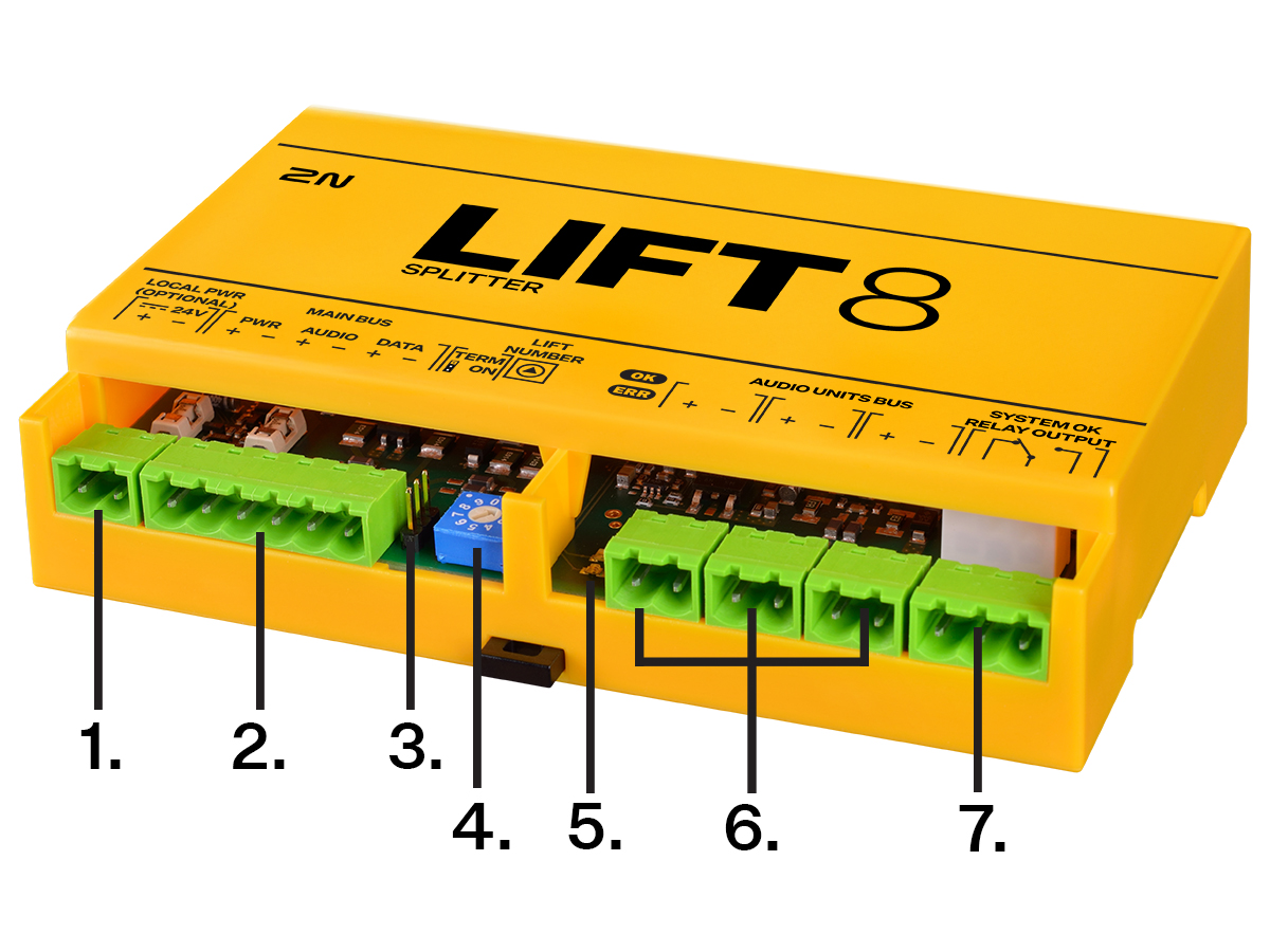
- Local power (optional)
- Main bus (Power, Audio, Data)
- Termination Resistance
- Lift number
- 2 control LEDs
- Audio unit terminals
- NO/NC relay for blocking of the lift
2N Lift8 Splitter
Caution – upgrade
- Set the splitters to odd addresses (lift/shaft number) for 1.x.x to 2.x.x upgrade as even addresses cannot be upgraded. Example: First upgrade the odd address splitters. Then disconnect these spliters and change the even address splitters to odd ones. After upgrade, change the odd addresses back to even ones.
- The upgrading process is indicated by green and red flashing LEDs (OK and ERR respectively).
Caution
- Local power supply is not supported yet.
Electrical Installation
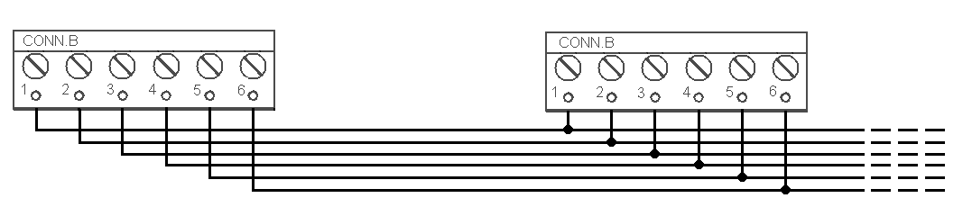
Main Bus Connection
Remove the push-in terminal board from the main bus connector and connect six wires from the CU maintaining the polarity (power + −, audio + −, data + −). See the printed figure on the splitter cover.
Main bus |
|---|
1 … Main bus power + |
2 … Main bus power − |
3 … Main bus audio + |
4 … Main bus audio − |
5 … Main bus data + |
6 … Main bus data − |
 |
Warning
- Maintain the connection polarity to avoid a 2N Lift8 error.
Bus Connection between Audio Units and Splitter
Interconnect the splitter and audio units using a two-wire bus maintaining polarity.
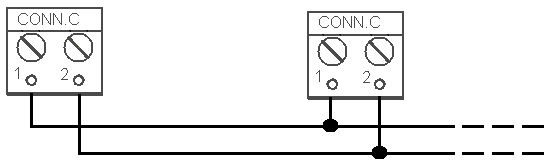 |
Audio unit bus |
|---|
1 … Bus for Audio Units + |
2 … Bus for Audio Units − |
Splitter Address Setting
Set the splitter address to 2 through 8 using the 10-position switch.
Configure lift 2–8 as 2–8 (set the switch to position 5 for lift 5, e.g.).
Warning
- Do not configure the splitter address as 0, 1 and 9 to avoid an error report from the system.
- Address 1 is used by the Central Unit.
Audio Unit Connection
Up to 8 audio units can be connected to one splitter. The splitter is equipped with 3 terminal boards for audio unit connection.
- Remove the slide-on terminal board from the audio unit connectors and connect the double wire.
- Connect 3 audio unit at most to one terminal board.
- Maintain the polarity to avoid audio unit malfunction. Refer to the splitter and audio unit prints for the connection polarity.
Wiring Requirements:
- The maximum length of the two-wire circuit connected to one splitter is 600 m, including all movable parts (towing cable).
- Where a towing cable is used, use the neighboring cables and make sure that the nearest neighboring conductors are not a source of interference. If shielded cables are used, connect adjacent conductors to the shielding.
- If you use multicore cables, always use a pair.
Do not lead the bus in a close vicinity of power cables, via a long distance in particular.
- It is not advisable to lead the bus near the wires connected to the elevator drive.
- You can branch the bus, especially to shorten the total length of all sections.
- A shielded cable is recommended in the case of increased interference. With a shielded cable, the shielding should be continuously connected along the entire cable route. The shielding must be connected to a suitable ground point, preferably to the Central Unit grounding.
Tip
Should bus communication problems occur, check the connection between the audio unit and the splitter (on the CU) using a two-wire lead via an alternative route far from potential interference sources.
Warning
- The bus is electrically isolated from the telephone line circuits according to the EN60950 standard requirements and its low voltage cannot cause any electrical accident.
Lift Blocking Function Connection
The function is not intended for use in the Evacuation mode.
The elevator blocking contact opens in the case of a phone line failure (PSTN, GSM, UMTS, VoIP, LTE) or before the complete discharge of the 2N Lift8 Central Unit batteries.
Connect the contact to the relevant input of the control electronics of the lift/group of lifts. The control electronics must ensure that, after the contact opening, the lifts in operation go down to the nearest station and the doors open.
Caution
This function may be mandatory depending on the regulations applicable in the country at the time of installation.
Termination Resistance,
- A 3-pin termination resistor setting jumper is located between the main bus connection and the lift number setting.
- It is necessary to put the jumper in the ON position on the Central Unit and the last device connected to the bus (splitter or I/O module).
- In the Evacuation mode, the I/O module is not used and the jumper is mounted to the ON position on the Central Unit and the last splitter.
- The termination jumper must be in the OFF position on the other devices that are not in the first/last position on the bus.
- The jumper on the splitter on the termination resistor is factory set to OFF.
 |
 |
Termination Resistance ON
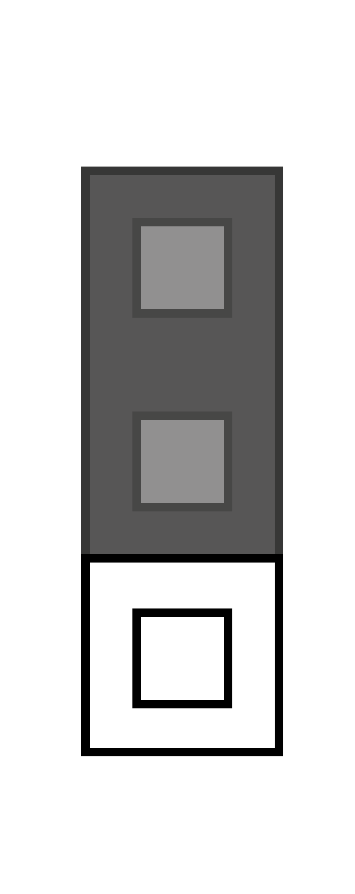 |
Termination Resistance OFF
Termination Resistance ON
Mounting Types
See below for the mounting types and necessary components. Install the device on sites not exposed to water leakage or condensation.
Wall Mounting
Use appropriate wall plugs and screws for mounting (not included in the delivery). Hang the device using the pre-drilled holes on the device bottom.
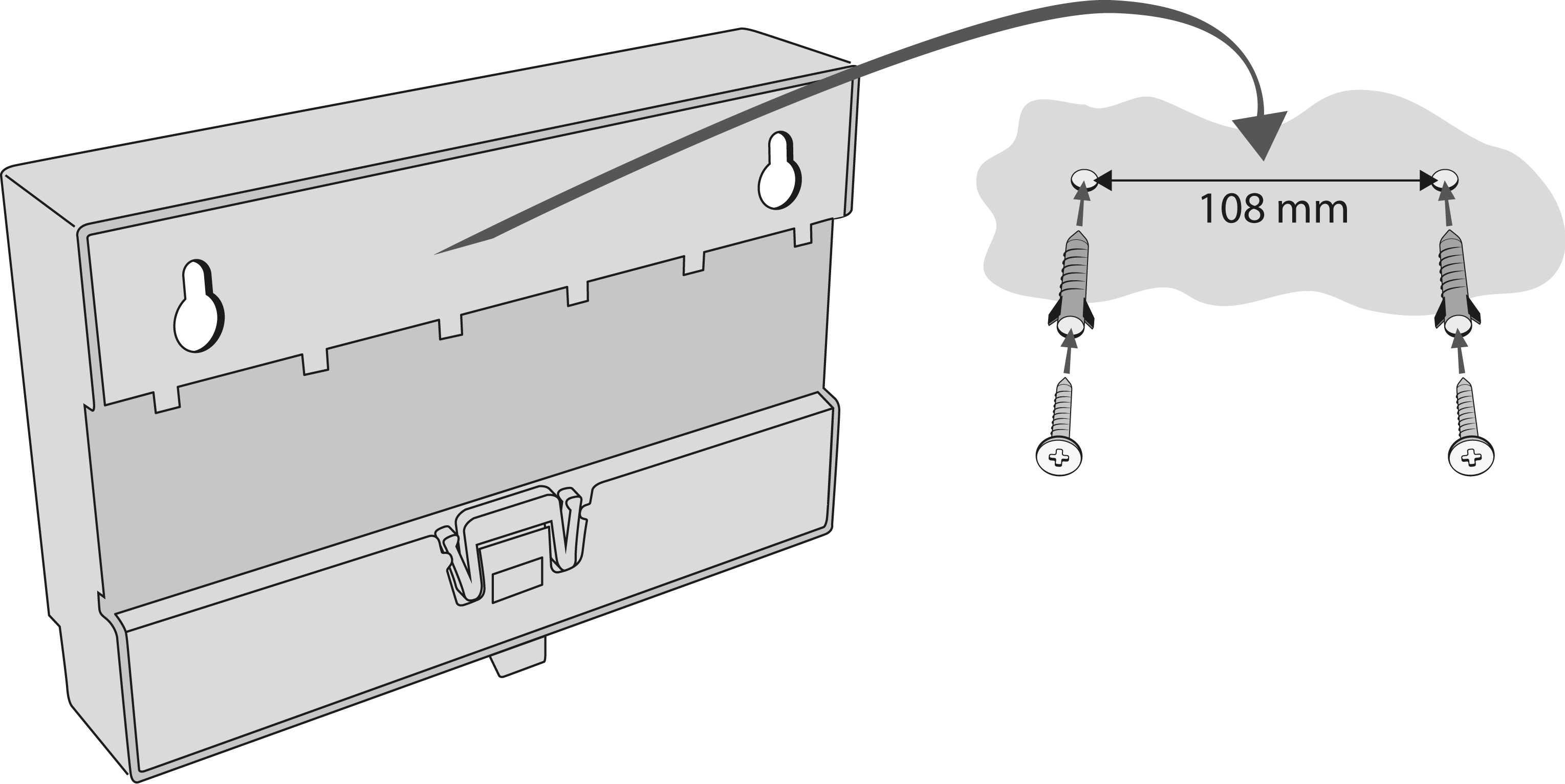 |
Wall Mounting
DIN Rail Mounting
It is possible to mount the device on a standard DIN rail TS 35. The minimum rail length is 14 cm.
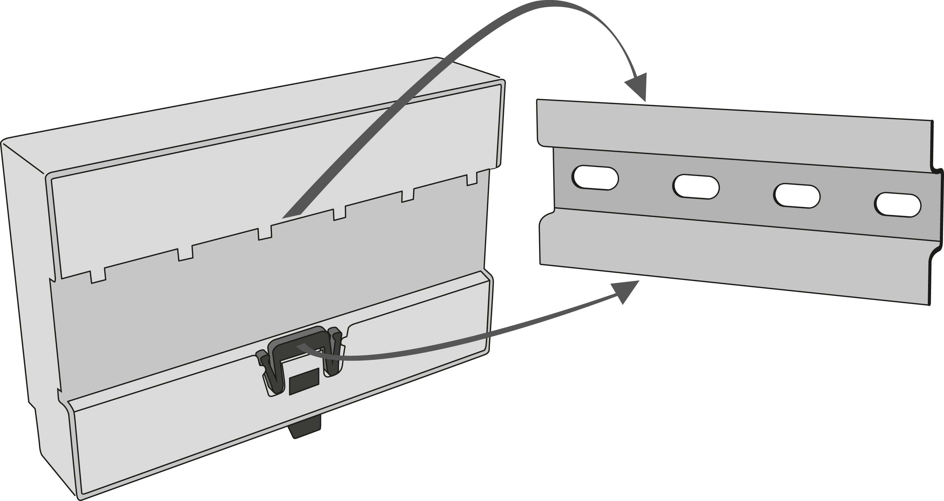 |
DIN Rail Mounting
Caution
- The warranty does not cover any defects or failures of the product arisen as a result of improper mounting in contradiction to these instructions.
- A wrong mounting procedure may lead to damage to the electronics due to water infiltration. The splitter circuits are constantly under voltage and water leakage causes electrochemical reaction. No warranty can be claimed for products damaged in this manner!