2.3 Mounting
Safety Precautions
Caution
- Make sure that the position, appearance and marking of the communicator controls (ALARM button, e.g.) are in accordance with the applicable lift standards.
Before You Start
Installation Conditions
- Make sure that the lift panel is ready for installation, including speaker perforation.
- The panel must include the following prescribed elements:
- ALARM button;
- Request accepted illuminated pictogram;
- Connection established illuminated pictogram.
- Make sure that the location of the elements meets the standard requirements.
- Leave free space behind the panel of 65 (W) x 130 (H) x 25 (D) mm.
2N® LiftIP 2.0 Position
Mount 2N® LiftIP 2.0 into any position as needed. The optimum position of 2N® LiftIP 2.0 is approximately at the adult’s mouth height. 2N® LiftIP 2.0 is designed for places where any touch of the operating personnel is excluded (refer to Security Precautions).
Caution
- We recommend that the electronics is not mounted without the mounting panel, otherwise the manufacturer cannot guarantee safety. The panel provides electrical insulation.
2N® LiftIP 2.0 Electronics Panel Mounting
What you need to mount the electronics panel onto the lift button panel:
- 4 spot-welded M4 screws from the inside with a pitch of 57 (W) x 122 (H) mm;
- sufficiently perforated speaker area – may be larger than as shown in the figure but may never exceed the panel size to avoid acoustic fault;
- microphone hole
- holes for 2 LEDs if necessary
Mounting Drawing for 50 mm Speaker Installation
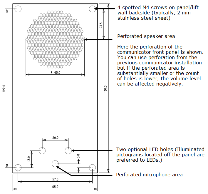
If you do not use the prescribed screws, make sure that the minimum isolation distance between the electronics and non-standard fixing elements is 2 mm. Mount the panel in such a manner that it does not resonate during the product function. Make sure that there is no gap between the button panel and 2N® LiftIP 2.0 panel or seal the gap if any properly to avoid the speaker acoustic fault and speaker – microphone acoustic feedback (see later).
Caution
- Make sure that microphone hole is sealed properly to record only sounds from the cabin instead of the noise from the shaft or space behind the panel.
2N® LiftIP 2.0 TOC Design Installation
The TOC version is designed for lift cabin wall mounting. Fit the metal cover onto screws that are smaller than the hole of the diameter 0.8 mm if possible. Use screws with flat surfaces alone or cone-head screws combined with the appropriate washer. Place the device on the selected installation site, mark the screw holes.
Caution
- If you use screws larger than recommended, the device may not be easily removed without unscrewing the screws.
- Or, if you use smaller screws than recommended, the device may not be fitted properly.
Off-Panel Microphone Mounting
By default, the microphone is located directly on the 2N® LiftIP 2.0 PCB (refer to the drawing for location). In cable versions, the external microphone is attached to a holder with a diameter of 25 mm and self-adhesive foil, the microphone is typically connected to the appropriate motherboard connector via a cable. The sticker helps you mount the microphone behind any button panel hole (the minimum hole diameter is 3 mm or the hole is composed of smaller holes of the same area). The external microphone connection state does not change during the device operation. The current external microphone state is detected at the device start/restart only. The minimum center-to-center distance between the speaker and the microphone is 90 mm. A shorter distance may lead to acoustic feedback. A longer distance does not matter.
Warning
- Make sure that the microphone hole is sealed against the noise that might get into the microphone through the gap between the cabin wall and the mounting panel. The microphone is supposed to receive sounds from the cabin only and not from the shaft or the 2N® LiftIP 2.0 installation cavity!
Off-Panel Speaker Mounting
Typically, the speaker is connected to the appropriate motherboard connector via a cable. The cable length enables the device to be placed within 1 m from the 2N® LiftIP 2.0 motherboard. In this case, mind the electrical safety, see below!
Caution
- Installing the speaker separately, make sure that the grid does not surpass the speaker dimensions in any case to eliminate the acoustic fault between the speaker front and back sides!
Accident Risk
- Make sure that the 50mm speaker is mounted on an insulating (non-metal) surface. Otherwise, request an external panel, see the figure below (not included in the delivery).
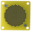 |
Caution
- We do not recommend you to install the microphone and speaker on completely different cabin sites (ceiling and wall, e.g.) as the users should find the speaker (grid/perforation) easily and then speak into the microphone near it.
Caution
- Should there be an acoustic feedback between the microphone and the speaker (echo), turn down the speaker volume.
How to Achieve Ideal Acoustic Properties
To ensure the minimum acoustic pressure according to the EN 81-28:2015 standard requirements, the holes in the communicator speaker covering panel should occupy 20 % of the speaker area at least and be placed in front of the speaker.
Make sure that the speaker and the microphone fit tightly to the covering panel. If this is impossible due to an uneven panel surface, we recommend that a speaker seal is used to avoid sound leaking into the space behind the panel. A good microphone sealing is crucial for high-quality sound transmission and good intelligibility.
Try to minimize the microphone - speaker acoustic feedback while mounting.
Indicator Mounting
There three types of 2N® LiftIP 2.0 state indicators:
- Illuminated pictograms are part of the cabin control panel.
- LEDs located directly on the 2N® LiftIP 2.0 electronics.
- Two LEDs (yellow, green) connected to the 2N® LiftIP 2.0 electronics in the cable version.
Note
- Make sure the selected type of indication meets the applicable legislation. However, no indication elements are necessary for the main function of 2N® LiftIP 2.0 (communication).