2.4 Connection
2N® LiftIP 2.0 Connection
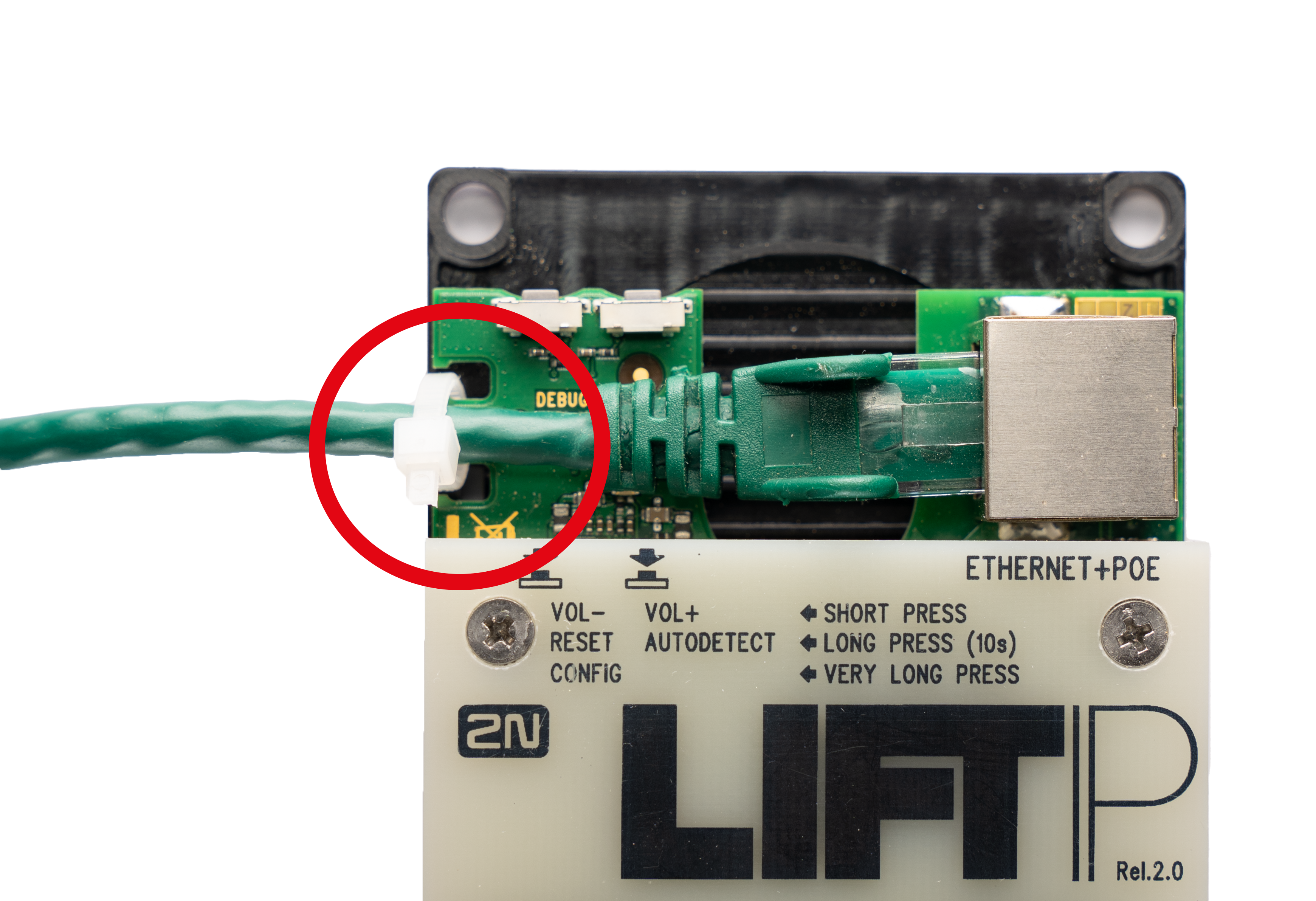
2N® LiftIP 2.0 is connected to the LAN via a Cat-5e or higher UTP cable terminated with RJ-45 (LAN connector). 2N® LiftIP 2.0 can be fed via PoE or from an external power supply (10–30 V DC, 0.5 A). Once connected to the LAN, 2N® LiftIP 2.0 gets the IP address from the DHCP server.
Or, retrieve the IP address using 2N® Network Scanner, which includes the network scanner. Refer to 2N® LiftIP 2.0 LAN Location via 2N® Network Scanner for more details.
By default, 2N® LiftIP 2.0 receives DTMF via RFC-2833 or in-band / SIP INFO detection.
Caution
- Fit the Ethernet cable to the motherboard using a cable tie to prevent mechanical stress of the connector.
ALARM 1/2 Connection – Contact Control
Accident Risk
- Remember that the button must be safe – the button contacts may never be connected to any other circuits. If such conditions cannot be met, use voltage control.
- Connect the button contacts to the ALARM terminal. The alarm is set as N/O (both jumpers mounted) from the factory.
- The button can have an N/O or N/C contact. If the case is a N/C contact, invert the button function in the device web configuration, refer to 4.5.2 Digital Inputs.
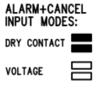
ALARM 1/2 Connection – Voltage Control
Tip
- DC voltage of 5–48 V can be used. Such source, however, must be backed up against power outage.
- Voltage connection / disconnection is used for activation. The alarm is set to contact control from the factory.
- Slide all the jumpers off the configuration jumper link to control alarm by voltage connection.
Warning
- Keep polarity (see the cover print).
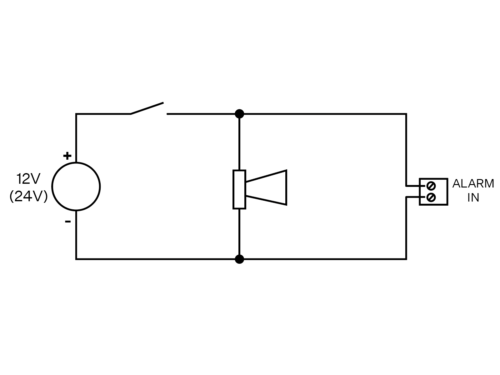
Tip
- Here is an example of wiring of an alarm button with a siren:
 |
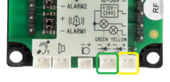
Indicator Connection
Basic connection
Any indicators can be used in this connection mode (illuminated pictograms, e.g.). The indicator brightness intensity is ensured by the use of an external power supply. 2N® LiftIP 2.0 includes just switches; connect a circuit to limit the current if necessary if LEDs are used.
 Requirements
- 12 - 24 V supply (backed up if the indicators are supposed to work at power outage).
- 200 mA permanent current (even with bulbs).
- Make sure that both the indicators are connected!
Warning
- Keep the power supply polarity!
Use of LEDs mounted on 2N® LiftIP 2.0 electronics
In this case, the LEDs are mounted on the electronics board and no additional connection is needed.
Cable connected LEDs
Used where no illuminated pictograms are available. Such LEDs are part of the device cable version accessories. They are LEDs with the diameter of 5 mm and very high luminosity.
 Requirements
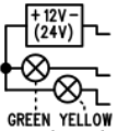
- Keep the LED polarity (see the cover print).
- Keep the colors: request confirmation – yellow, connection confirmation – green.
Note
- The printed circuit LED is off in this type of connection.
CANCEL Connection (Door Contact, Optional)
Caution
- Make sure that the door switch or door opening signal indicates that the door is open only if both the internal and external lift doors are open and the people can leave the cabin.
Switch control
- Connect the switch to the CANCEL terminal.
- The 2N® LiftIP 2.0 is set to contact control from the factory. Both the jumpers are mounted on the configuration jumper.
- CANCEL can be set to N/C contact too. If the case is a N/C contact, invert the CANCEL input function in the device web configuration, refer to 4.5.2 Digital Inputs.
Voltage control
DC voltage ranging from 5 to 48 V can be used.
- Slide both the jumpers off the configuration jumper link for voltage control.
- To use voltage disconnection control, invert the CANCEL input function in the device web configuration, refer to 4.5.2 Digital Inputs.
Caution
- If voltage presence signals a closed door, make sure that the power supply is backed up against power outage.
Warning
- Keep polarity (see the cover print).
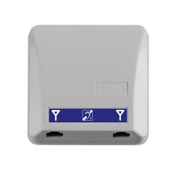
Induction Loop Connection
Follow the applicable regulations while mounting the communicator as they might require that the induction loop for deaf people should be a mandatory part of a lift cabin communicator installation. Connect the loop to the 2N® LiftIP 2.0 backside connector. Polarity is arbitrary. If agreed so, the induction loop can be part of the delivery including a 4m cable.
Requirements
- We recommend that the induction loop is located behind a non-magnetic cover to avoid the induction loop field radiation worsening.
- Make sure that the induction loop is marked with an appropriate pictogram (ear) and its position meets the standard requirements.