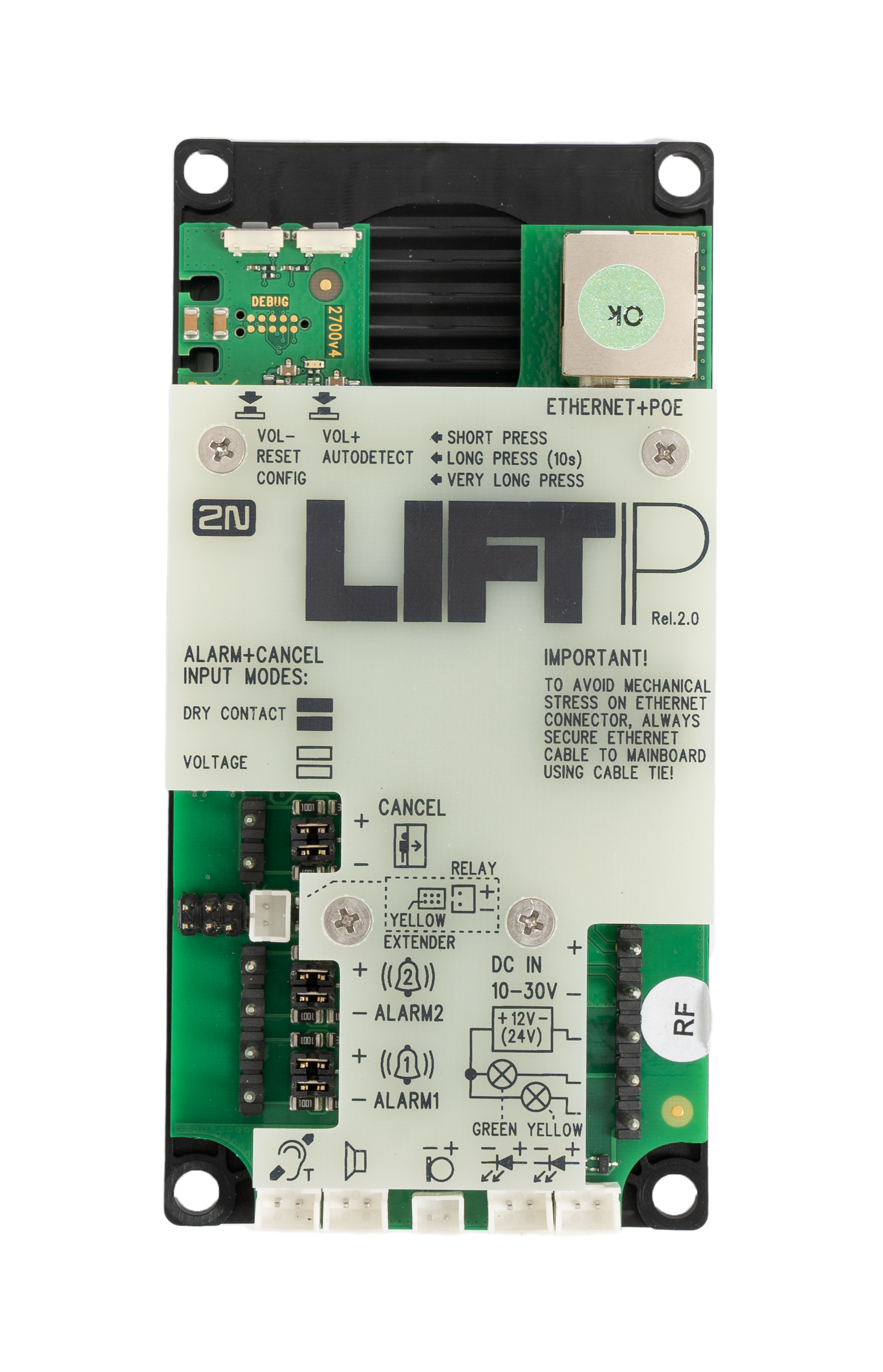
2.5 Description of Terminals, Jumpers, Connectors and LEDs
Description of terminals and connectors | ||||
|---|---|---|---|---|
Button VOL−, RESET, CONFIG | Short press (VOL−) − turn down the speaker volume Long press (RESET) – restart the device in approx. 10 s Very long press (CONFIG) − retrieve the device IP address, switch the static / dynamic IP address mode and reset the factory default values | |||
Button VOL+, AUTODETECT | Short press (VOL+) − turn up the speaker volume Long press (AUTODETECT) – set the default ALARM 1/2 input polarity in approx. 10 s | |||
| ETHERNET + POE | RJ-45 (PoE according to802.3af) LAN connector | |||
| DC IN 10–30 V terminal | External power supply (unless PoE is available) | 10–30 V DC | ||
| Indicator connecting terminals + 12 V (24 V) | 12–24 V DC / 2× 200 mA externally supplied indicators; keep the wiring diagram. | |||
| “Connection establishing” LED connector | Yellow | The LEDs are not a standard part of the delivery (available only in cable versions). | ||
| “Connection established” LED connector | Green | |||
| External microphone connector | The external microphone connection state does not change during the device operation. The current external microphone state is detected at the device start/restart only. | |||
| Speaker connector | The speaker is connected in the standard delivery. | |||
Induction loop connector | The induction loop is not a standard part of the delivery. It must be installed behind an non-conductive and non-magnetic cover. Polarity does not matter.
| |||
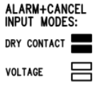
ALARM 1/2 terminal | Contact control | N/O contact (default) | Use the configuration jumpers for setting. N/O contact: both the jumpers are mounted. | |
N/C contact | N/C contact: both the jumpers are mounted and input polarity is inverted in the software configuration in S. 4.4.2 Input Inversion. | |||
Voltage control | Connect DC voltage of 5–48 V. | Voltage connection control: no jumper is mounted and input polarity is inverted in the software configuration in S. 4.4.2 Input Inversion. | ||
Disconnect DC voltage of 5–48 V. | Voltage disconnection control: no jumper is mounted. | |||
RELAY connector | 2N® LiftIP 2.0 Relay extender connector | |||
YELLOW EXTENDER (6-pin connector) | Used for 2N® Voice Alarm Station connection. | |||
CANCEL terminal | Contact control | N/O contact (default) | Use the configuration jumpers for setting. N/O contact: both the jumpers are mounted. | |
N/C contact | N/C contact: both the jumpers are mounted and input polarity is inverted in the software configuration in Subs. 4.4.2 Input Inversion. | |||
Voltage control | Connect DC voltage of 5–48 V. | Voltage connection control: no jumper is mounted and input polarity is inverted in the software configuration in S. 4.4.2 Input Inversion. | ||
Disconnect DC voltage of 5–48 V. | Voltage disconnection control: no jumper is mounted. | |||
Warning
- Keep polarity for voltage-controlled ALARM and CANCEL buttons (see the instructions on the cover).
Caution
- Should there be an acoustic feedback between the microphone and the speaker (echo), turn down the speaker volume.
LED (front side – during call)
| Color | Status | Function | Description |
|---|---|---|---|
| Yellow | Light on | Establishing call | Signals alarm call connecting process and rescue mode in progress if enabled. |
| Green | Light on | Connection established | Signals alarm call connection with the option to talk to the counterparty. The alarm call is confirmed, the incoming call is answered. |
Yellow + green | Alternately flashing | Checking call failure | Checking call failure signaling Another call is signaled when it starts, see the cases above. Once the call ends, flashing is restored. An error state is terminated by alarm call confirmation (ALARM1 only) or a subsequent successful checking call. |
No light | Relax | Signals the device relax state. | |
Note
- The LEDs are located on the 2N® LiftIP 2.0 audio unit front side.
- External LEDs can be connected too (Establishing connection, Connection established).


