2.3 Electric Installation
Electric Installation Step by Step
It is very easy to connect 2N® SIP Audio Converter electrically. Follow the steps below to avoid equipment damage or electrical injury:
- Connect the microphone, loudspeaker, headset or external amplifier.
- Connect the digital input and output.
- Connect the UTP cable.
- Connect a 12 V power supply (unless PoE is used).
Caution
- Be sure to connect the 2N® SIP Audio Converter power supply as the last step. The same applies to PoE supply from the LAN.
Loudspeaker Connection
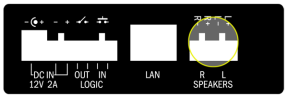
2N® SIP Audio Converter is equipped with a power amplifier for 1 or 2 loudspeakers. The loudspeakers to be used must have the nominal impedance of 4–8 Ω each. Refer to the table below for possible configurations and related maximum power outputs (sinus, THD < 1 %):
Loudspeaker(s) | 12 V / 2 A | PoE |
|---|---|---|
Two 4 Ω | 2x 10 W | 2x 5 W |
Two 8 Ω | 2x 9 W | 2x 5 W |
One 4 Ω | 1x 18 W | 1x 10 W |
One 8 Ω | 1x 12 W | 1x 10 W |
Caution
Use an external power supply to maximise the power output. Make sure that the maximum Master volume value is +6 dB in the Hardware / Audio menu if you use PoE and 4Ω speaker.
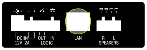
Use the R + and L − or L + and R − terminals.
  |
Loudspeaker Connection
Headset/External Amplifier Connection
2N® SIP Audio Converter is equipped with a headset/external amplifier output. The 3.5mm jack is available on the front panel.
  |
Audio Output Connection
Microphone/Line Connection
2N® SIP Audio Converter is equipped with a microphone/external supply output. The 3.5mm jack is available on the front panel. Use electret microphone for connection.
  |
Audio Input Connection
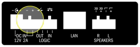
Digital Output Connection
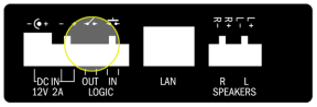
2N® SIP Audio Converter is equipped with a passive output relay switch for light signalling/external amplifier/alarm activation. The output is available on terminals marked LOGIC OUT and allows for switching of up to 24 V / 1 A AC/DC loads. By default, the output is in the NO (normally open) state.
  |
Digital Output Connection
Warning
- Do not exceed the upper voltage and current limits to avoid irreversible damage of the equipment.
Warning
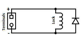
When you connect a device containing a coil, such as a relay or an electromagnetic lock, it is necessary to protect the intercom against voltage peak while switching off the induction load. For this way of protection we recommend a diode 1 A / 1000 V (e.g., 1N4007, 1N5407, 1N5408) connected antiparallel to the device.
 |
Digital Input Connection
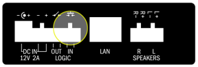
2N® SIP Audio Converter is equipped with a digital input for an optional button. This input is available on the LOGIC IN terminal. Only external contact needed.
  |
Digital Input Connection
LAN Connection
2N® SIP Audio Converter can be connected to a standard local area network using a LAN interface via the RJ-45 connector on the back panel. Always use CAT-5d or higher class cables for reliability reasons.
  |
LAN Connection
The LAN interface is equipped with the Auto MDIX function for automatic straight/cross-over cable detection.
The LAN interface can also be used for the 2N® SIP Audio Converter power supply through active network elements or injectors meeting the IEEE 802.3af standard.
Note
- With PoE, the integrated amplifier power output is limited to 10 W. To utilise the maximum power output of the amplifier, feed 2N® SIP Audio Converter from a 12 V DC / 1.8 A external power supply.
Caution
- We recommend the use of a LAN surge protection.
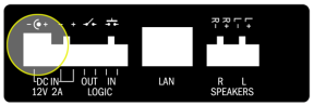
Power Supply Connection
2N® SIP Audio Converter can be fed using active network elements or PoE injectors via the LAN interface. In case this option is unavailable, use a 12 V DC / 2 A (Part No. 914102E) power supply or another power supply on condition that you keep the nominal values included in the Mechanical and Electrical Parameters subsection.
Connect the 12 V DC power supply either to the back panel supply connector marked DC IN, or terminals marked DC IN + and DC IN –.
  |
  |
Power Supply Connection
Warning
- If you use an adapter other than the recommended one, do not exceed the nominal supply voltage value of 12 V. Also make sure that the supply voltage polarity is correct. Exceeding nominal values and/or incorrect connection may lead to irreversible damage of the equipment.