2.1 Description
2N® SmartCom PRO consists of a PCB carrying a power supply and RS 232, RS 485/M–Bus/MDB interfaces. An optional GSM/UMTS module provides continuous Internet connection via GPRS/UMTS. Two relays are available for output contact control. Connectors for optional devices are located in the upper part of 2N® SmartCom PRO. Refer to the figures below for description. There is a gel–lead–acid accumulator connector on the bottom panel. The board also includes a real time clock backup and optional Wireless M-Bus and ZigBee modules. An optional Ethernet connector is mounted on the bottom too. Refer to the figures below for details. The whole 2N® SmartCom PRO system is enclosed in a solid aluminium case. Mount the case on a DIN rail for easier installation.
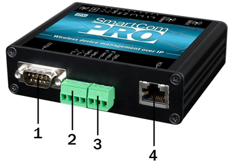 |
2N® SmartCom PRO Description (Bottom View)
- RS 232 connector
- 9-pin D-sub
- Power supply and battery terminal board
- + Uin, - Uin – input supply voltage terminals
- + Batt, - Batt – gel–lead–acid accumulator terminals
- RS 485/M-Bus/RS232 connector (bus type according to the selected version)
- +,-,GND for RS 485
- A,B,GND for M-Bus
- Ethernet interface (optional)
- RJ-45
 |
2N® SmartCom PRO Description (Top View)
- ZigBee antenna SMA connector (optional)
- Wireless M-Bus antenna SMA connector (optional)
- Input/output circuit terminal board (from left):
- RE1 – closing relay contacts
RE2 – switching relay contacts
Uin+, Uin- – auxiliary supply voltage contacts, used e.g. for connecting supply voltage to the relays (galvanically connected to the Uin+, Uin– contacts on the 4–pin power supply connector on the bottom side)
- GND – ground used with the IN1 and IN2 input circuits
- IN1, IN2 – input circuits (input type according to the jumper settings, refer to Subs. 3.3)
- Signalling LEDs
- from left: ZigBee, WM-Bus, GSM/UMTS or ETH as configured
- SIM holder
- GSM/UMTS antenna SMA connector