3.4 Input Calibration
A 10-bit A/D converter is connected to the IN1 and IN2 input terminals, which converts the measured value to a number ranging between 0 and 1023. Practically, the 0 - 1020 range is used; the remaining three steps are used for overvoltage detection.
The purpose of calibration is to compensate the inaccuracy of components and external factors and to ensure that the 960 value of the A/D converter matches exactly 10 V in each input. The value usually oscillates slightly around this point. Let us give an example: suppose you place two terminals next to each other under identical external conditions. One terminal will measure 966 and the other 957 for 10 V. Calibrate the input to eliminate such inconsistency.
Note
- Keep in mind that an uncalibrated input is not non-functional. It is able to measure and read values less precisely, but sufficiently for rough voltage or current detection.
For calibration, use the terminals and AT commands described in Sub. 4.2, or the Terminal Config tool - refer to Sub. 4.3 - for setting and application details. The following figure shows the calibration diagram and basic principle. The meanings of the curves are explained below.
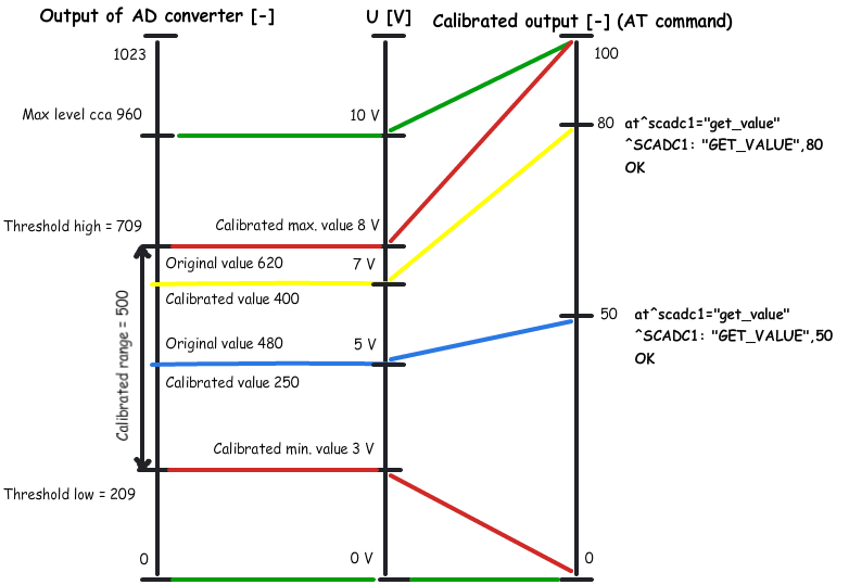 |
Figure: Calibration Diagram
– The green lines indicate that no calibration has been made yet. The A/D converter works in the whole range and deviations may occur from the actual value measured on the input. If you, in this situation, set Threshold low to 0V and Threshold high to 10V on the input, the terminal will be calibrated for 10V precisely. For 0 on the input, the AT command will return 0. For 10, we obtain 100. Thus, the calibrated input can be considered 0–100% of the calibrated range.
– The red lines mean that the input has been calibrated to the interval of 3 to 8V, i.e. to the range of 5V. This range now represents new measurement limits. If you apply 3V or less on the input, you are in the calibrated min area and the AT command will return 0. If you apply 8V or more, you are in the calibrated max area and the AT command will return 100. This means that the measured range width has narrowed by 50% and 0–100% is now mapped to the input range of 3–8V.
– The blue line is an example of measuring in the calibrated range of 0 to 10V. Apply precisely one half of the calibrated voltage, i.e. 5V, to the input. The AT command will return 50, i.e. one half of the 0–100 range again. In this case, 5V is the centre of the calibrated range. If, however, the range was shifted, the value would be shifted too as shown below.
– The yellow line shows the case that 7V is applied to the input. In case you measure 7V in the calibrated 10V range, the AT command will return 70 as 70 represents 70% of the calibrated range. But if the range is just 3 to 8V as in the red case, 7V will represent 80% of the calibrated range of 5V and the AT command will return 80.
Caution
- If you use the calibrated input for reading logic values, keep in mind that the calibrated area is considered unstable. Values lower than the set minimum will be 0 and those exceeding the maximum will be 1. No value is guaranteed in an unstable area and a spurious state change may occur any time in the interval. Practically, the decisive level is near the middle of the set interval.