3.3 Input and Output Circuits
This subsection describes the input and output circuits of 2N® SmartCom PRO including their main use, control and location.
Tip
- 2N® SmartCom PRO is equipped with reliable terminals for easier and faster connection.
- Refer to S. 6 for a full AT command list.
Input Circuits
2N® SmartCom PRO is equipped with three inputs, which are mutually galvanically connected with the GND reference point (have a common GROUND). Remember to keep the parameters specified in the Technical Parameters at the end of this manual.
The input circuits can work in three modes – voltage, current or logical levels – as configured.
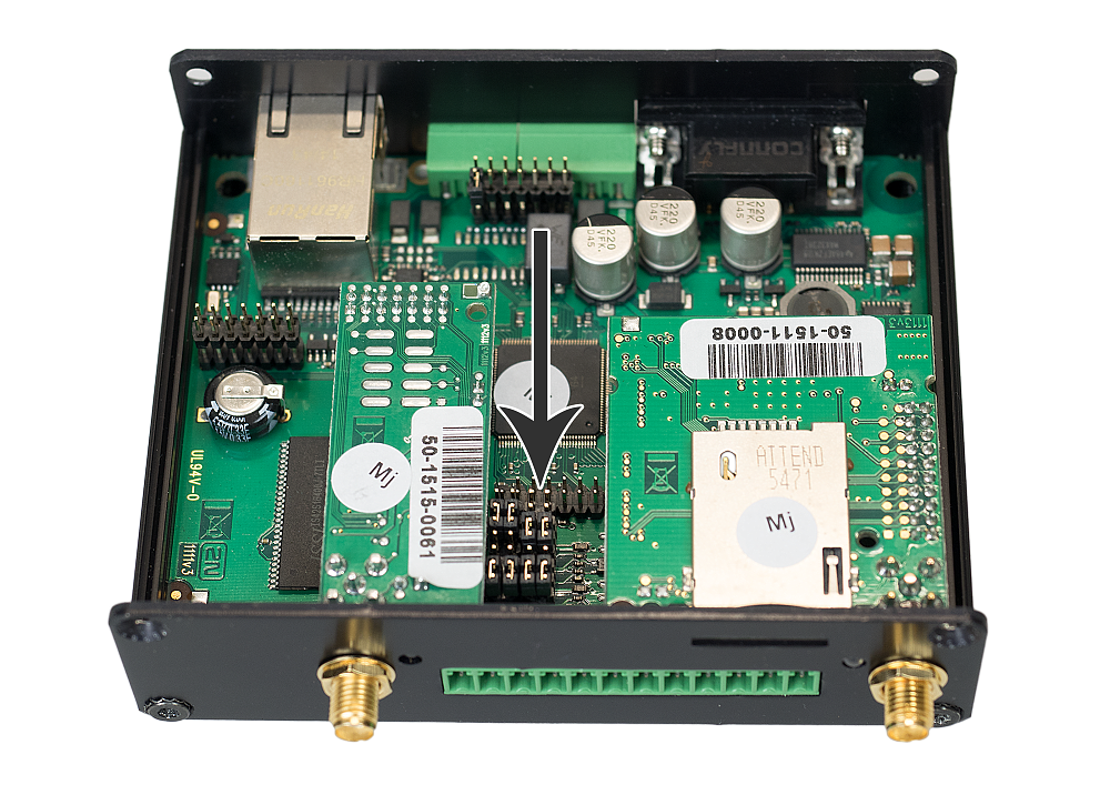
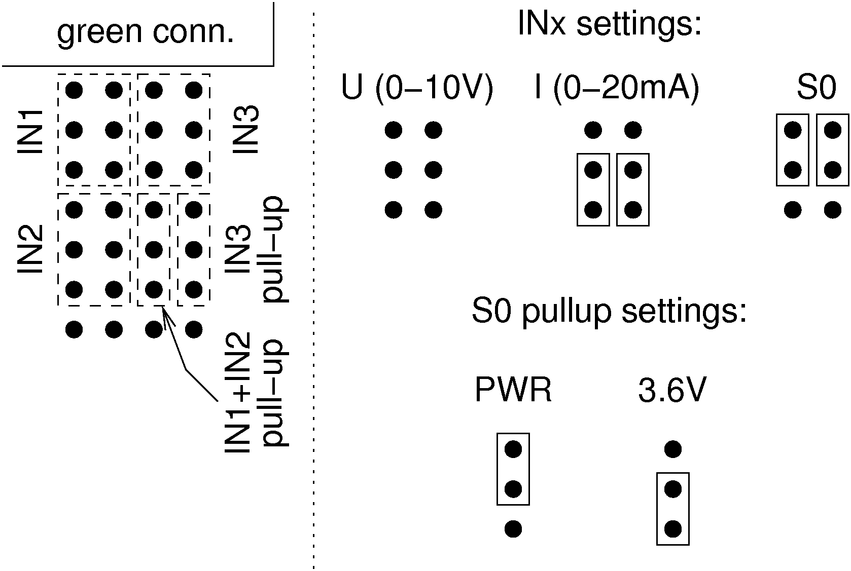
The figures below show the location of the current/voltage/S0 switching jumpers. Loosen the screws and open the box lid to get access to the PCB jumpers. See the figure below for the mode setting options.
Caution
- Disconnect 2N® SmartCom PRO from the power supply before opening the cover. Be careful while handling the jumpers to avoid device destruction!
|
Jumper Setting
Voltage Measurement
Voltage can be measured in the range between 0 and 10 V DC. Make sure that the
2N® SmartCom PRO jumpers are set as shown in the figure above before using this mode. Use the AT commands listed below for reading and calibration.
Current Measurement
Electric current can be measured in the range between 4 and 20 mA. Make sure that the 2N® SmartCom PRO jumpers are set as shown in the figure above before using this mode. Use the AT commands listed below for reading and calibration. These commands control the input circuits, set calibration and perform measurement. An example is given for the ADC circuit 1 (scadc1). To read circuit 2, replace 1 with 2 in the command (scadc2).
at^scadc1="get_value"
- The command performs measurement on the selected interface and sends the calibrated value measured.
at^scadc1="adc_value"
- The command performs measurement and returns the value from the A/D converter.
at^scadc1="calib_min"
- Automatic interface calibration according to the currently measured value.
at^scadc1="calib_max"
- Automatic interface calibration according to the currently measured value.
at^scadc1="threshold_low",1200
- Manual calibration setting (minimum values). Setting options: 0–4090.
at^scadc1="threshold_high",3250
- Manual calibration setting (maximum values). Setting options: 0–4090.
at^scadc1="save"
- The command saves the changes.
Logical Level Monitoring
You can monitor the logical levels of voltage and current signals. Use other commands than those intended for classic measurements and define the threshold levels. Again, use the AT commands for reading values on input circuits.
at^scdin1="get_value"
- The command detects the logical level on the selected interface and sends the value 1/0.
at^scdin1="calib_min"
- Automatic interface calibration according to the currently measured value.
at^scdin1="calib_max"
- Automatic interface calibration according to the currently measured value.
at^scdin1="threshold_low",1400
- Manual calibration setting (minimum values). Setting options: 0–4090.
at^scdin1="threshold_high",3450
- Manual calibration setting (maximum values). Setting options: 0–4090.
at^scdin1="save"
- The command saves the changes.
Pulse Counting on S0 Inputs
Make sure that the jumpers are set as shown in the figure below for pulse counting on S0 inputs. The S0 input has thus a power supply of its own and can be connected directly to the switch or relay contacts. The counter is disabled by default and has to be enabled using the AT commands listed below. The commands are used for setting and reading of the S0 input pulse counter states. You can increase the S0 bus resistance against interference if necessary by connecting PullUp voltage from the power supply or an internal 3V6 supply.
at^scpulse1="state"
- The command detects the current states of the input 1 counters.
- COUNTING – counting in progress.
- STOPPED – counting stopped.
at^scpulse1="get_value"
- The command reads out the counter state.
at^scpulse1="set_value",100
- The command sets the counter pulse count (100 in this case) if you do not want to start from zero. Setting options: 0–4294967295.
at^scpulse1="stimer",60
- The command sets the EEPROM storing intervals for the counter in seconds. Setting options: 5–10000 s.
at^scpulse1="start"
- The command starts counting on input 1.
at^scpulse1="stop"
- The command stops counting on input 1.
at^scpulse1="clear"
- The command clears the input 1 counter.
at^scpulse1="save"
- Manual storing of the counter value into the EEPROM.
Output Circuits
2N® SmartCom PRO is equipped with two relay outputs for turning on/off electrical appliances (by an additional power switch or as signalling control inputs, depending on their power input). Remember to keep the parameters specified in the Technical parameters at the end of this manual.
You can control the relay outputs with the AT commands from the CMD mode of the RS 232 interface, via a remote GPRS connection to the SIM card IP address, or using an SMS message. Refer to Subs. 4.2 for AT command details and S. 5 for SMS configuration details.
Caution
- Attention! Any manual setting is valid until the next change or device power off. 2N® SmartCom PRO does not keep in mind the relay settings by default and restores the default status upon power up.
- Set the parameter determining the relay position upon power up to 2 to make your 2N® SmartCom PRO remember the relay position. Thus,
2N® SmartCom PRO shall remember the last contact position before disconnection. Refer to the configuration subsections for more details.
Relay Outputs
Use the commands below to control the relay outputs. An example is given for relay 1. For relay 2, use the same commands but for screl2.
at^screl1?
- The commands detects the state of relay 1.
at^screl1=0
- The command opens relay 1.
at^screl1=0,0
- The command opens relay 1. The relay will be open upon the terminal restart.
at^screl1=0,1
- The command opens relay 1. The relay will be closed upon the terminal restart.
at^screl1=0,2
- The command opens relay 1. Upon terminal restart, the relay will be in the state in which it was before restart.
at^screl1=1
- The command closes relay 1.
at^screl1=1,0
- The command closes relay 1. The relay will be open upon the terminal restart.
at^screl1=1,1
- The command closes relay 1. The relay will be closed upon the terminal restart.
at^screl1=1,2
- The command closes relay 1. Upon terminal restart, the relay will be in the state in which it was before restart.
RS 232 and RS 485/ M-Bus Interfaces
Find the interface connectors on the bottom side of 2N® SmartCom PRO. Refer to Subs. 2.1. A 9-pin D-sub connector is used for RS-232 and a 3-pin WAGO terminal is used for RS 485 or M-Bus located on the bottom panel next to the power supply terminals. Follow the wiring instructions on the label. Use the commands below to set the RS 232 port parameters. Use the same commands to set the other ports but change the port address (scport2).
at^scport1="baudrate",9600
- The command sets the baud rate to 9600 bps.
- The default baud rate value is 115200 bps.
at^scport1="baudrate",230400
- The command sets the baud rate to 230400 bps.
- Set the baud rate in standard steps from 110 to 230400.
at^scport1="data_bits",8
- The command sets the data bit count to 8.
- Setting options: 5–8.
at^scport1="stop_bits",2
- The command sets the stop bit count to 2.
- Setting options: 1–2.
- Setting options: 1–2.
at^scport1="parity",2
- The command sets the parity security type.
- 0 – none
- 1 – even
- 2 – odd
- 3 – constant 1
- 4 – constant 0
at^scport1="flowcontrol",1
- The command sets the flow control type.
- 0 – no flow control
- 1 – hardware flow control
at^scport1="save"
- The command saves the changes.
at^scport1="restart"
- The command restarts the interface.
at^scport1="srestart"
- The command saves the changes and restarts the interface.