2.3 Product Description
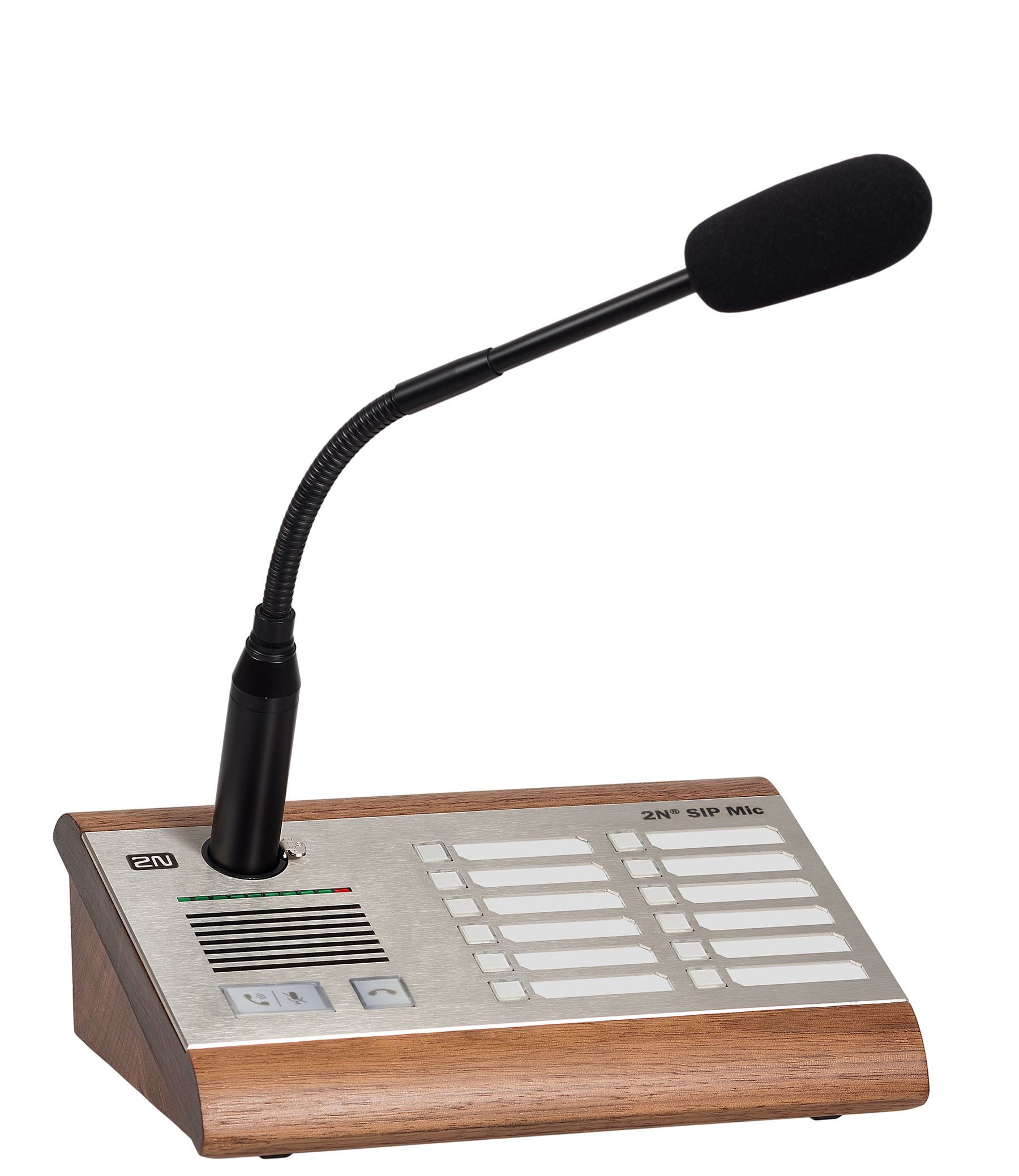
2N® SIP Mic is an Ethernet SIP console designed for public sound distribution. 2N® SIP Mic can be connected to a SIP Proxy and communicate with the server via phone calls. This guarantees compatibility with all the supported SIP-based systems.
Use an integrated web interface for 2N® SIP Mic configuration. Apply the 2N® Network Scanner to search all the 2N® SIP Mic units connected.
Control Layout
 |
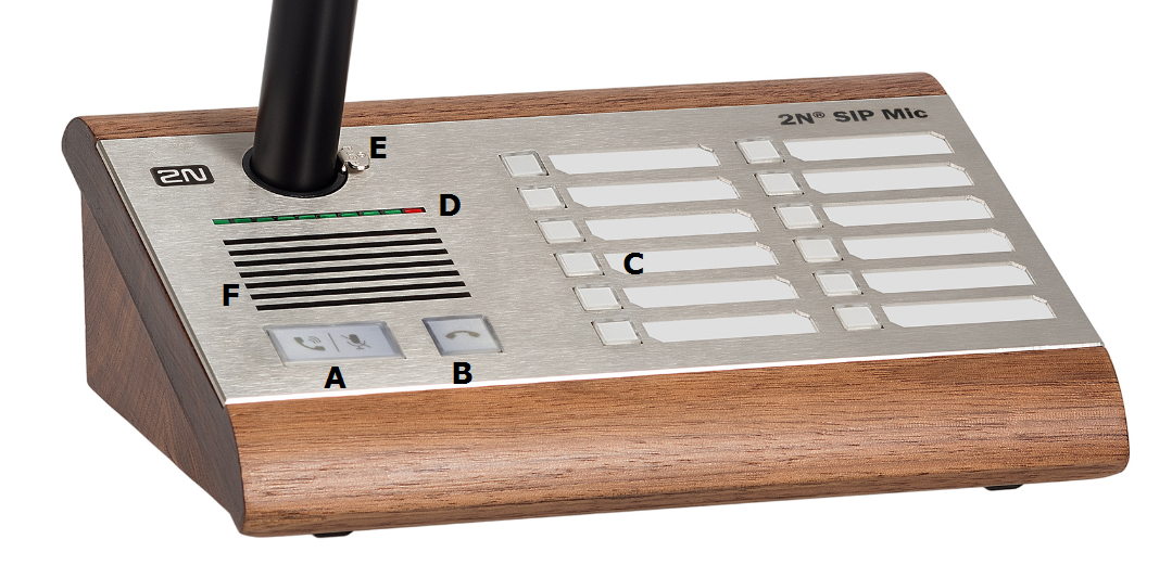
2N® SIP Mic Controls
Legend:
- A ... call answer / mute button
- B ... call extension button
- C ... function buttons 1 to 12 for playing/announcing to zone
- D ... bar graph – microphone drive indicator
- E ... microphone DIN connector
- F ... integrated speaker
 |
2N® SIP Mic Controls
Button Function States
Each button is backlit. Different backlight colours signal different user states. See below.
Call pick-up / Mute button
| Colour | Behaviour | State | Action upon press |
|---|---|---|---|
| White | Shining | At relax | None |
| Green | Flashing | Incoming call ringing | Answer call |
| Green | Shining | Active incoming call | Mute microphone |
| White + (red hang-up) | Shining | Muted | Turn up microphone |
| Yellow | Shining | Active message recording | End recording |
| Blue | Shining | Active outgoing call | Mute microphone |
Call hang-up button
| Colour | Behaviour | State | Action upon press |
|---|---|---|---|
| White | Shining | At relax | None |
| Red | Shining | Incoming / Outgoing call | Hang up / Reject |
Function buttons
| Colour | Behaviour | State | Action upon press |
|---|---|---|---|
| White | Shining | At relax | None |
| White | Flashing | Message playing | End playing |
| Blue | Flashing | Outgoing call ringing | End call |
| Blue | Shining | Active outgoing call / Zone announcement | End call / End zone announcement |
| Green | Flashing | Outgoing ALARM call ringing / DTMF request | None (cannot be terminated) / End call |
| Green | Shining | Outgoing ALARM call ringing / DTMF request | None (cannot be terminated) / End call |
| Pink | Shining | HTTP request sent | Return to relax |
| Yellow | Shining | Active relay contact | As configured, refer to Buttons |
| Yellow | Flashing | Active message recording | End recording
|
| Red | Shining | Call error or end | None, automatic end With Announcement after message you can skip over the announcement and end the call immediately. |
Connector Layout
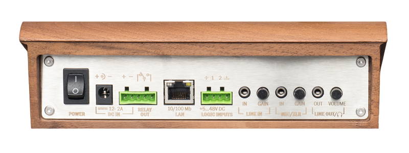 |
2N® SIP Mic Connectors
Connectors and controls:
- power on/off button
- 12 V DC / 2 A mains adapter connector
- relay output
- LAN – 10/100BASE-TX RJ-45 connector
- logic inputs
- line input – 3.5 mm jack for optional external sound source connection
- MIC input – 3.5 mm jack for optional microphone connection
- Line out – 3.5 mm jack for headset / external speaker connection
Refer to the Technical Parameters for more details.
Caution
- Pin 1 is the first logical input, isolated.
- Pin 2 is the second logical input, isolated.
- Pin + is connected with supply voltage (+7 V) and switches the logical input into "logical 1".
- Pin ꓕ means grounding (GND) and switches the logical input into "logical 0".
Tip
Pins 1 and 2 are processor-monitored logical inputs. They are switched to 1 when connected to + and to 0 when connected to the GDN ground. Make sure that pin + and pin 1 are connected via a switch or relay to make them work properly. The same applies to pin 2.
- IP address: 192.168.1.100
- Network mask: 255.255.255.0
- DHCP: ON
Refer to Subs. 3.1 Configuration for a change of the DHCP server setting.
 |