2.3 Electric Installation
This subsection describes how to install the modules and connect the 2N Access Unit to the power supply and LAN and how to connect other elements.
Version A – Stand-alone Access Unit
- Place the 2N Access Unit on the flush mounting box / pre-drilled holes with dowels and pull the cables through the bottom holes. Pull the Ethernet cable through the bottom hole to the left if necessary.
- Insert the metal fitting elements up and down and screw the access unit tight. You can level the unit slightly in this mounting type.
Version B – Access Unit with additional module
- Unscrew the upper part of the additional base – keypad, RFID reader, etc.
- Use a flat screwdriver to take the upper part out.
- Slide the additional module to the access unit. Secure its position with small side wedges and screws.
- Place the assembled modules on the flush mounting box / predrilled holes with dowels and pull the cables through the access unit bottom holes. Feed the Ethernet cable without the connector from the additional module to the access unit base if necessary.
Warning
- With 2N Access Unit 2.0, modules can be exchanged arbitrarily within a unit. With earlier versions (2N Access Unit 1.0), however, the whole unit must be replaced.
2N Access Unit
Power Supply Connection
2N Access Unit can be powered either from an external 12 V / 1 A DC source or directly from the LAN equipped with PoE 802.3af supporting network elements.
External power supply
For reliability reasons, use a 12 V ±15 % SELV supply dimensioned to the current consumption as required for feeding of the access unit and connected modules.
Current consumption [A] | Part No. | Available power output [W] |
|---|---|---|
| 1 | 91341482E, 91341482US | 12 |
PoE power supply
2N Access Unit is compatible with PoE 802.3af (Class 0–12.95 W) and can be fed directly from the LAN via the compatible network elements. If your LAN does not support this technology, insert a PoE injector, Part No. 91378100, between 2N Access Unit and the nearest network element. This power supply provides 2N Access Unit with 12 W for feeding of itself and the connected modules.
Combined power supply
2N Access Unit can be fed from an external power supply and PoE at the same time. In this configuration, the maximum power for the connected modules is available.
Varování
- 2N Access Unit 2.0 with HW version 599v4 and lower cannot be fed from an external power supply and PoE at the same time. A combined supply might result in a device damage.
LAN Connection
2N Access Unit is connected to the Local Area Network (LAN) via the UTP/STP cable (Cat 5e or higher) terminated with a terminal board as shown in the figure below. As the device is equipped with the Auto-MDIX function, either the straight or crossed cable can be used.
Caution
- We recommend the use of a LAN surge protection.
- We recommend the use of a shielded SSTP Ethernet cable.
Caution
There may be connectivity problems in 2N Access Unit version 586v2 if a cable longer than 30 m is used for LAN connection. If this happens, we recommend you to:
- integrate another network element (switch) to shorten the jump
- feed the device from an external 12 V supply
- change the PoE phantom supply (typically TP-LINK) to spare-pair supply – Phihong injector, Part No. 91378100
- change the Ethernet bitrate to Half Duplex – 10 mbps
Warning
-
This product cannot be connected directly to the telecommunications lines (or public wireless LANs) of any telecommunication carriers (e.g. mobile communications carriers, fixed communications carriers, or internet providers). In the case of connecting this product to the Internet, be sure to connect it via a router.
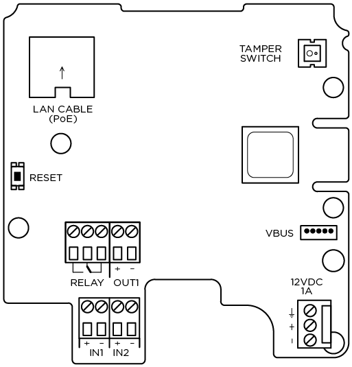
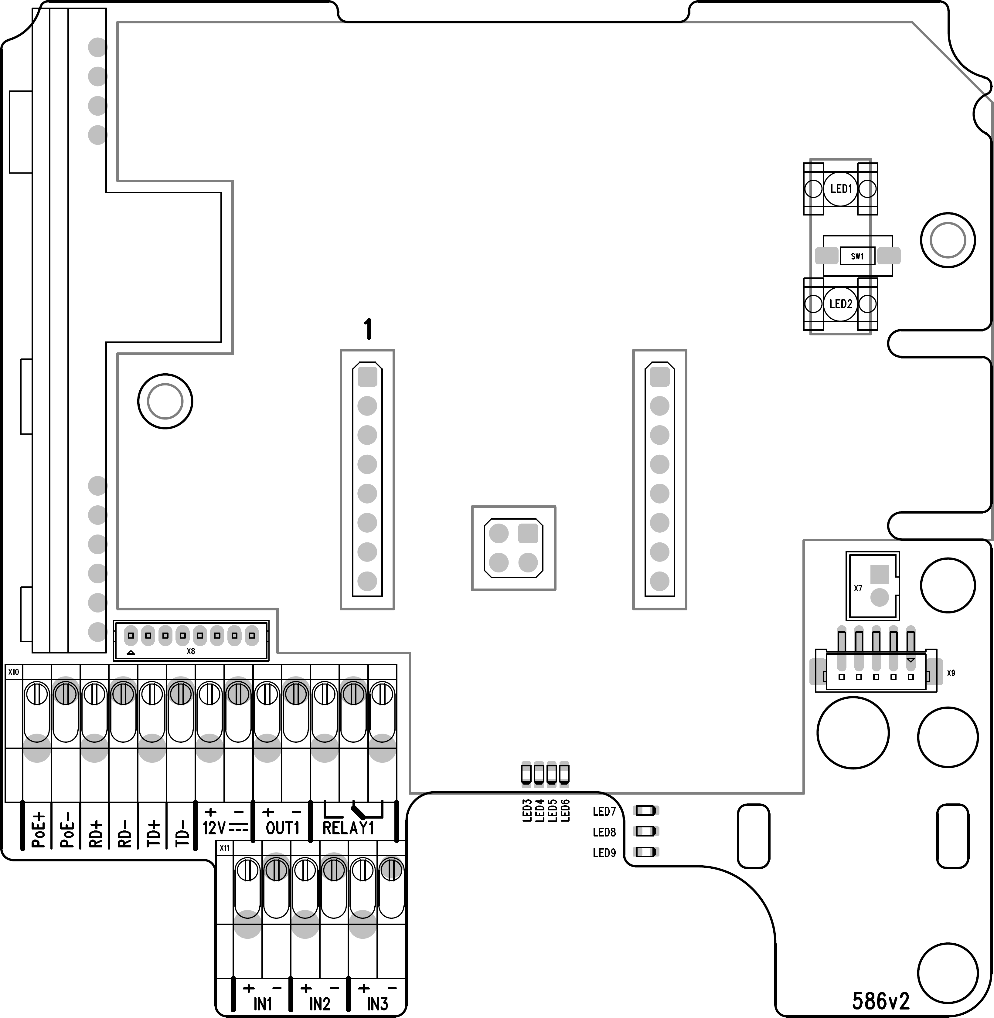
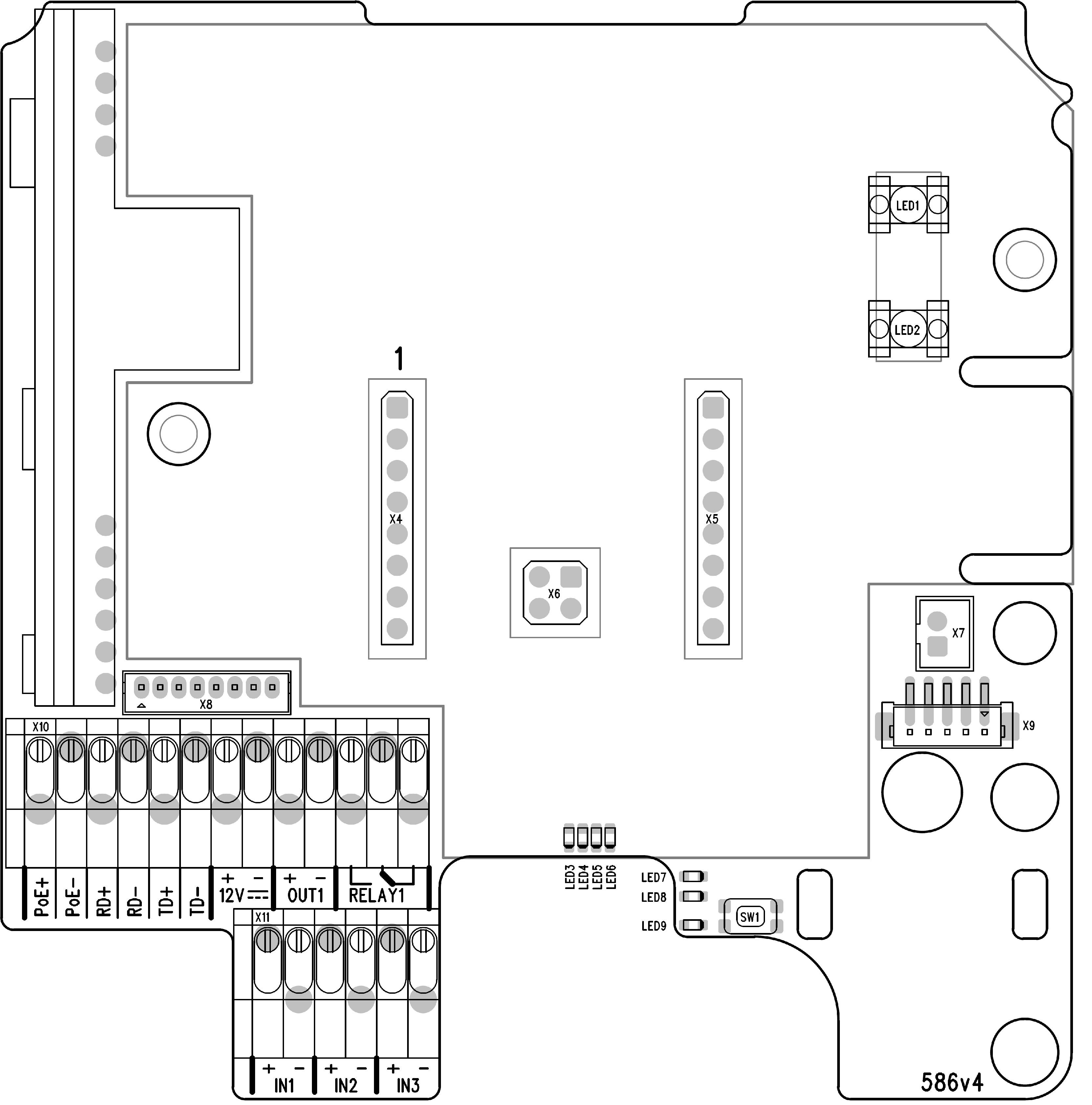
UTP Cable Connection to 2N Access Unit 2.0 Terminal Board
 |
UTP Cable Connection to 2N Access Unit Terminal Board
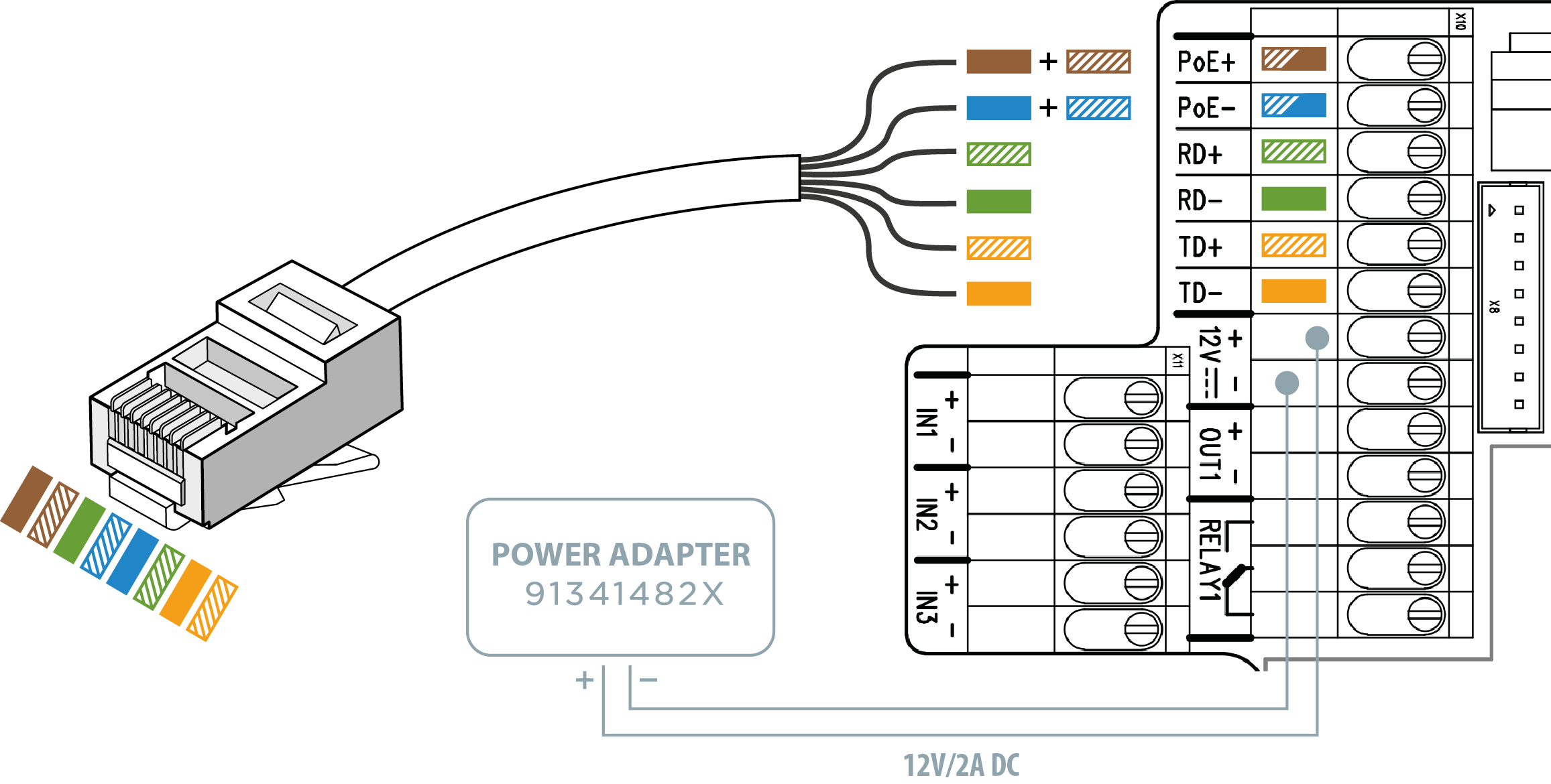 |
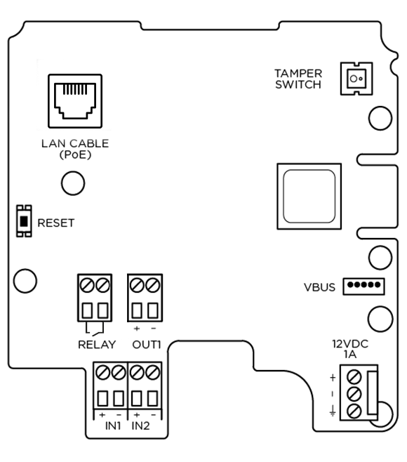
| Legend to Figure | |
PoE, RD, TD | LAN (PoE according to 802.1af) terminals |
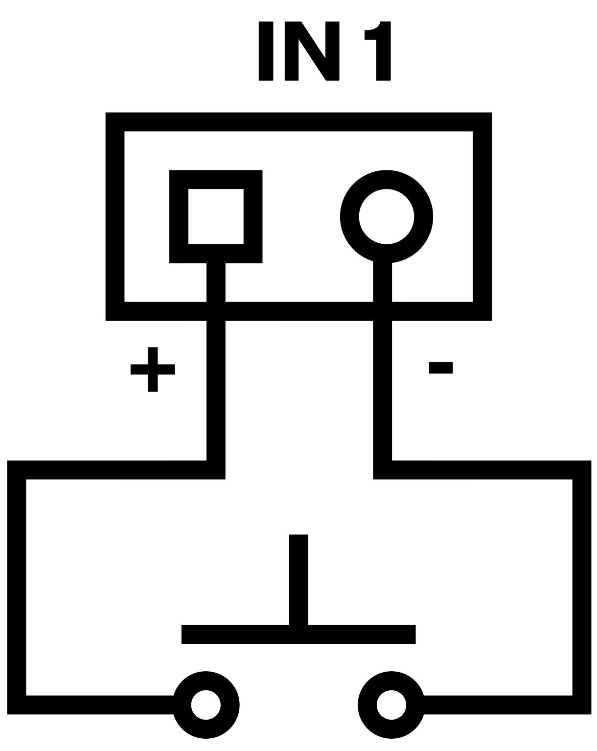
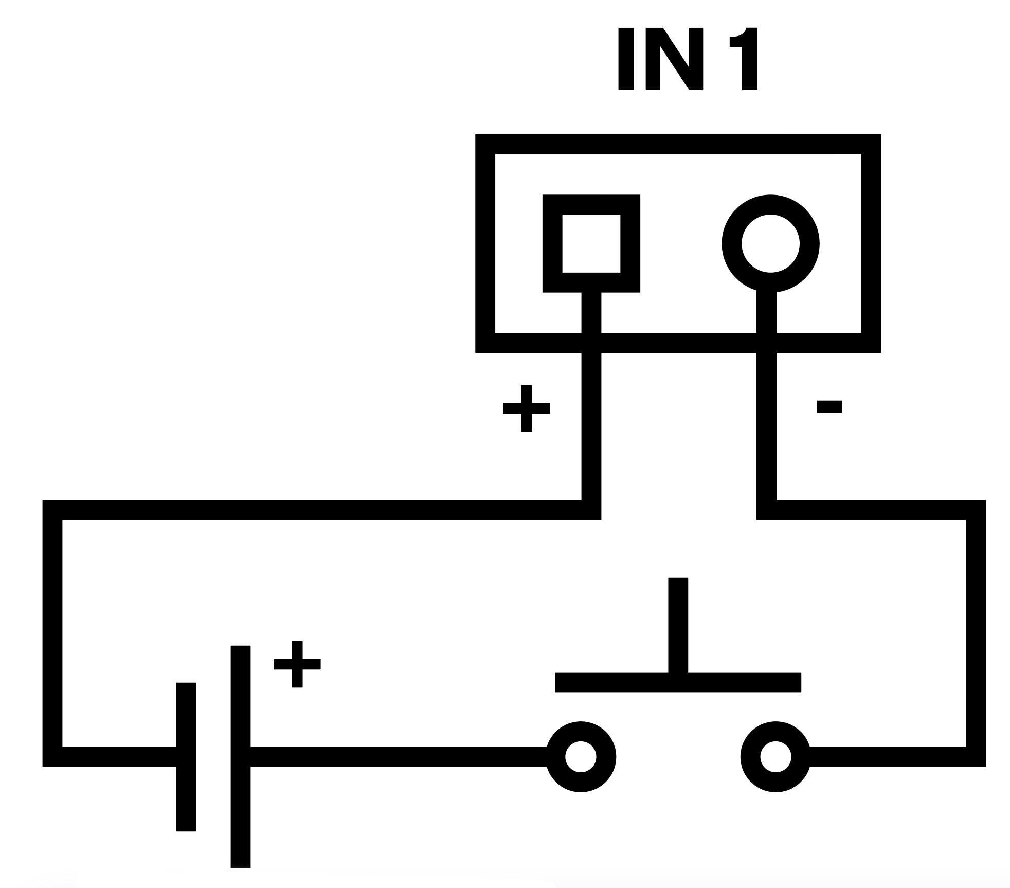
IN1, IN2, IN3 | IN1, IN2 and IN3 (available for 2N Access Unit 1.0 only) terminals used as an input in the passive/active mode (−30 V to +30 V DC) for departure button, open door sensor, ESS etc. connection
|
OUT1 | OUT1 active output terminals for connection of 2N® IP Security Relay or electric lock: 8 up to 12 V DC depending on power supply (PoE: 10 V; adapter: power supply voltage minus 2 V), up to 600 mA |
RELAY1 | PCB version 599v6 and higher:
PCB version 599v3 and 599v4:
PCB version 586v2 and higher:
|
12 V / 1 A | External supply terminals for 2N Access Unit – 12 V / 1 A |
RESET | RESET / FACTORY RESET button |
RJ-45 | RJ-45 adapter connector – no need to use the PoE, RD and TD terminals for this connector |
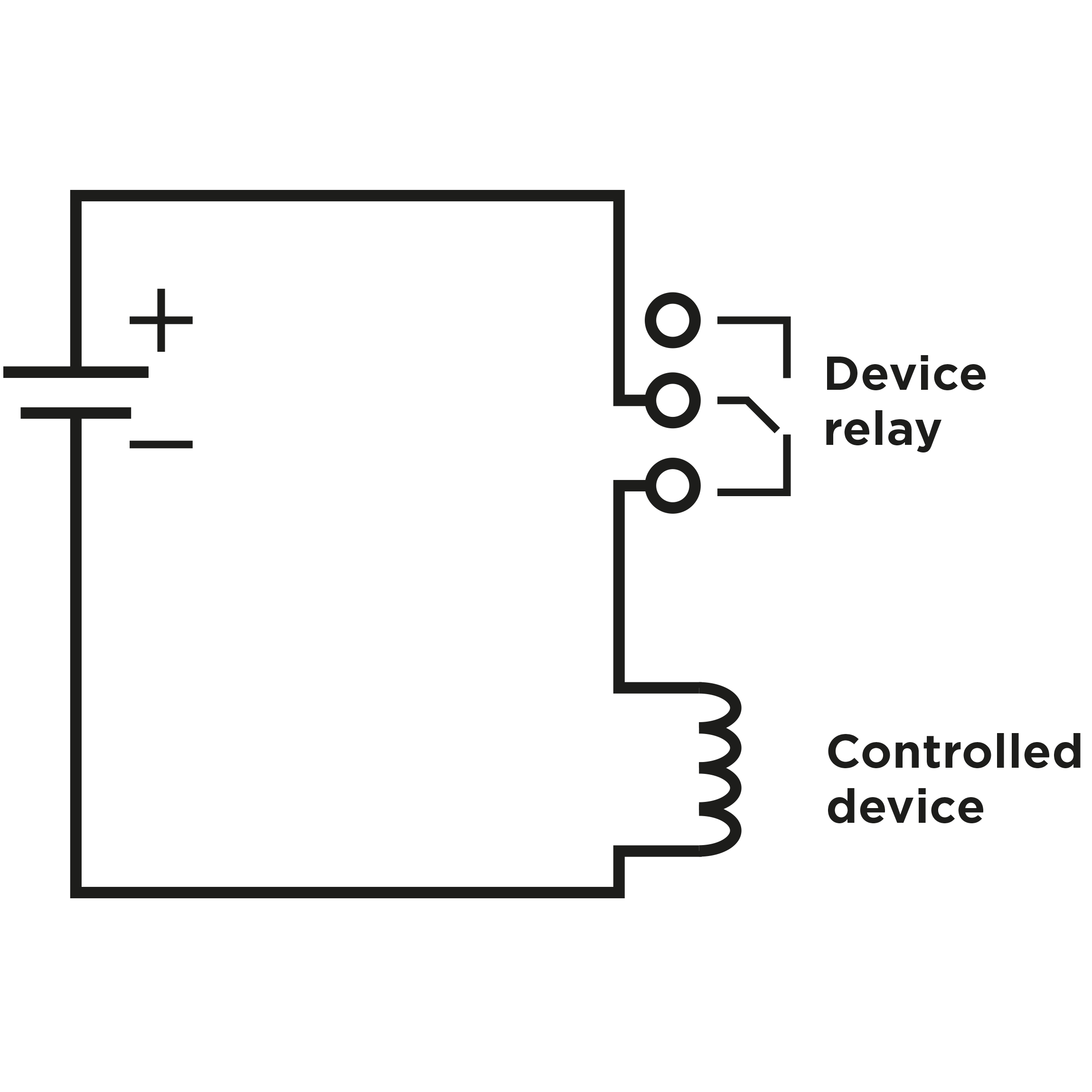
- Output wiring diagram for Relay terminals
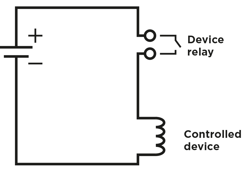 |
Electric circuit closing diagram for controlled devices with PCB version 599v6 and above
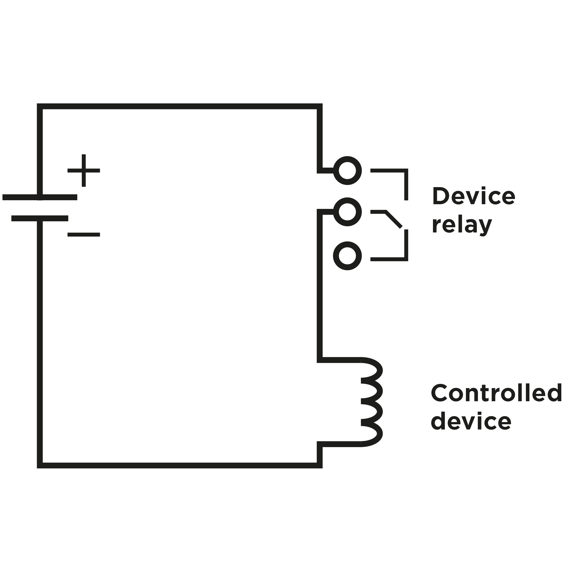 |
Electric circuit closing diagram for controlled devices with PCB version 586v2 and below
 |
Electric circuit opening diagram for controlled devices with PCB version 586v2 and below
Tip
- Wiring diagram of IN1, IN2 and IN3 terminals in active mode
 |
- Wiring diagram of IN1, IN2 and IN3 terminals in passive mode
 |
Reset Button
Located among the main unit connectors, the Reset button helps you reset the factory default values, restart the device, find the device IP address and switch the static/dynamic mode.
IP Address Retrieval
Follow the instructions below to retrieve the current IP address:
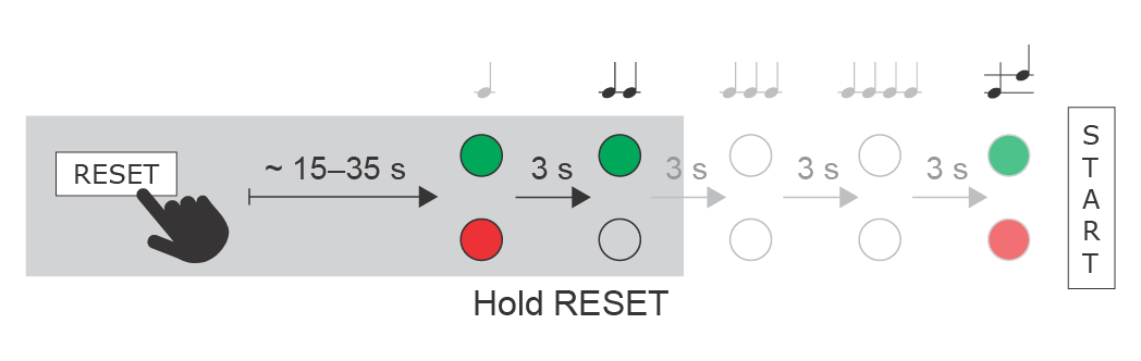
- Press and hold the RESET button.
- Wait until the red and green LEDs go on simultaneously on the device and the acoustic signal
 can be heard (approx. 15–35 s).
 - Release the RESET button.
- The device automatically announces the current IP address.
 |
Note
- The delay after pressing RESET till the first light and sound signalling is set to 15–35 s depending on the 2N IP intercom/answering unit model used.
- 42 s is a valid value for 2N Access Unit, 15 s is a valid value for 2N Access Unit 2.0.
Static IP Address Setting
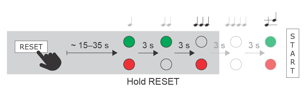
Follow the instructions below to switch on the Static IP address mode (DHCP OFF):
- Press and hold the RESET button.
- Wait until the red and green LEDs go on simultaneously on the device and the acoustic signal
 can be heard (approx. 15–35 s).
 - Wait until the red LED goes off and the acoustic signal
 can be heard (approx. for another 3 s).
 - Release the RESET button.
The following network parameters will be set after restart:
- IP address: 192.168.1.100
- Network mask: 255.255.255.0
- Default gateway: 192.168.1.1
 |
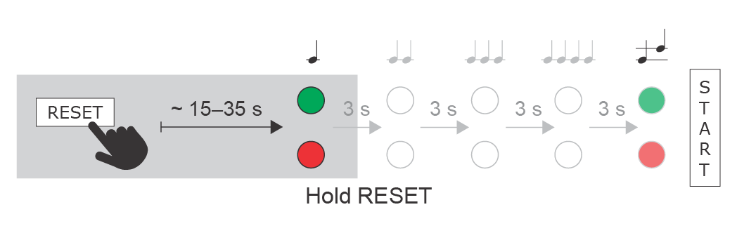
Dynamic IP Address Setting
Follow the instructions below to switch on the Dynamic IP address mode (DCHP ON):
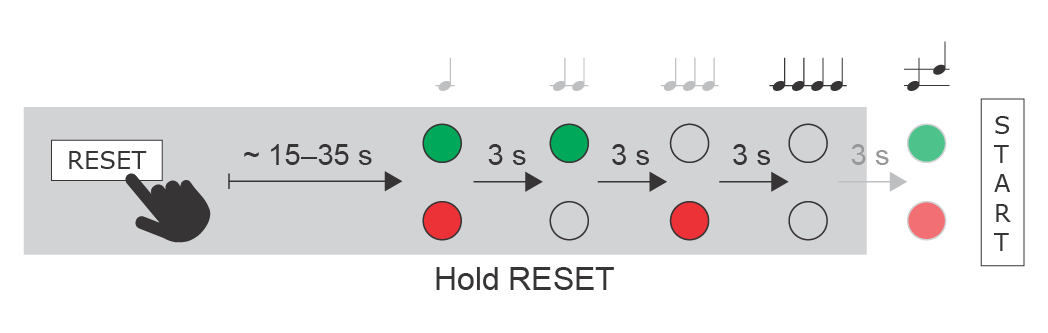
- Press and hold the RESET button.
- Wait until the red and green LEDs go on simultaneously on the device and the acoustic signal can be heard (approx. 15–35 s).
- Wait until the red LED goes off and the acoustic signal can be heard (approx. for another 3 s).
- Wait until the green LED goes off and the red LED goes on again and the acoustic signal
 can be heard (approx. for another 3 s).
 - Release the RESET button.
 |
Factory Reset
Follow the instructions below to reset the factory default values:
- Press and hold the RESET button.
- Wait until the red and green LEDs go on simultaneously and the acoustic signal can be heard (approx. 15–35 s).
- Wait until the red LED goes off and the acoustic signal can be heard (approx. for another 3 s).
- Wait until the green LED goes off and the red LED goes on again and the acoustic signal can be heard (approx. for another 3 s).
- Wait until the red LED goes off and the acoustic signal
 can be heard (approx. for another 3 s).
 - Release the RESET button.
 |
Caution
- In case of resetting the factory default settings on a device with a firmware version 2.18 or higher, it is necessary to reprogram the
2N® Security Relay using the instructions from Subsection 2.4.
2N Access Unit is equipped with a RESET button. The button is located in the left-hand part below the LAN connector in PCB version 599v6, between the LED indicators (LED1 and LED2 below) in the right-hand upper part of the unit in version 586v2 and in the middle of the lower part in version 586v4. Press the button shortly (< 1 s) to restart the system without changing configuration.
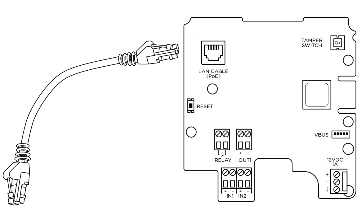
2N Access Unit 2.0 Connectors, PCB Version 599v6 |
Caution
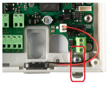
- The order of the power supply connector terminals has been changed on and a small grounding plate has been added to the PCB (version 599v6).
Warning
- Do not remove the small metal plate under the power supply connector. The plate is necessary for a proper metal frame grounding and its absence may compromise the resistance against electrostatic discharge.
 |
2N Access Unit Connectors, PCB Version 599v3 and 599v4 |
2N Access Unit Connectors, PCB Version 586v2 |
2N Access Unit Connectors, PCB Version 586v4 |
Device Restart
Press the RESET button shortly (< 1 s) to restart the system without changing configuration.
Note
- The time interval between the short press of RESET and reconnection after restart is 49 s for 2N Access Unit, 14 s for 2N Access Unit 2.0.
Available Switches
| Location | Name | Description |
|---|---|---|
| Basic unit | Relay 1 | PCB Version 599v6 and higher:
PCB Version 599v3 and 599v4:
PCB Version 586v2 and higher:
|
| Output 1 | Active switch output: 8 up to 12 V DC depending on power supply (PoE: 10 V; adapter: power supply voltage minus 2 V), up to 600 mA | |
| Tamper switch | Helps to secure the system against tampering. The information about unauthorised manipulation with the device can be used in the menu Hardware / Digital Inputs / Tamper Switch, in Automation a it is also logged in the Events. |
Security
- The 12V output is used for lock connection. If, however, the unit (2N IP Intercom, 2N Access Unit) is installed where unauthorized tampering may happen, we strongly recommend that the 2N® Security Relay (Part No. 9159010) be used for enhanced installation security.
Warning
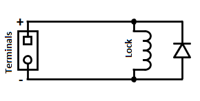
When you connect a device containing a coil, such as a relay or an electromagnetic lock, it is necessary to protect the intercom output against voltage peak while switching off the induction load. For this way of protection we recommend a 1 A / 1000 V diode (e.g., 1N4007, 1N5407, 1N5408) connected antiparallel to the device.
 |