2.4 Extending Module Connection
The Security Relay (Part No. 9159010) is used for enhancing security between the access unit and the connected electric lock. It significantly enhances security of the connected electric lock as it prevents unlocking by forced opening of 2N Access Unit M.
 |
Function:
The Security Relay is a device installed between the access unit (outside the secured area) and an electric lock (inside the secured area). The Security Relay includes a relay that can only be activated if a valid access card is detected by the unit.
Specifications:
Passive switch: NO and NC contacts, up to 30 V / 1 A AC / DC
Switched output:
- Where the security relay is fed from the intercom, 9 to 13 V DC is available on the output depending on the power supply (PoE: 9 V; adapter: source voltage of minus 1 V) / 400 mA DC.
- Where the security relay is fed from an external power supply, 12 V / 700 mA DC is available on the output.
Dimensions: (56 x 31 x 24) mm
Weight: 20 g
Installation:
The Security Relay is installed onto a two-wire cable between the access unit and the electric lock inside the area to be secured (typically behind the door). The device is powered and controlled via this two-wire cable and thus can be added to an existing installation. Thanks to its compact dimensions, the device can be installed into a standard mounting box.
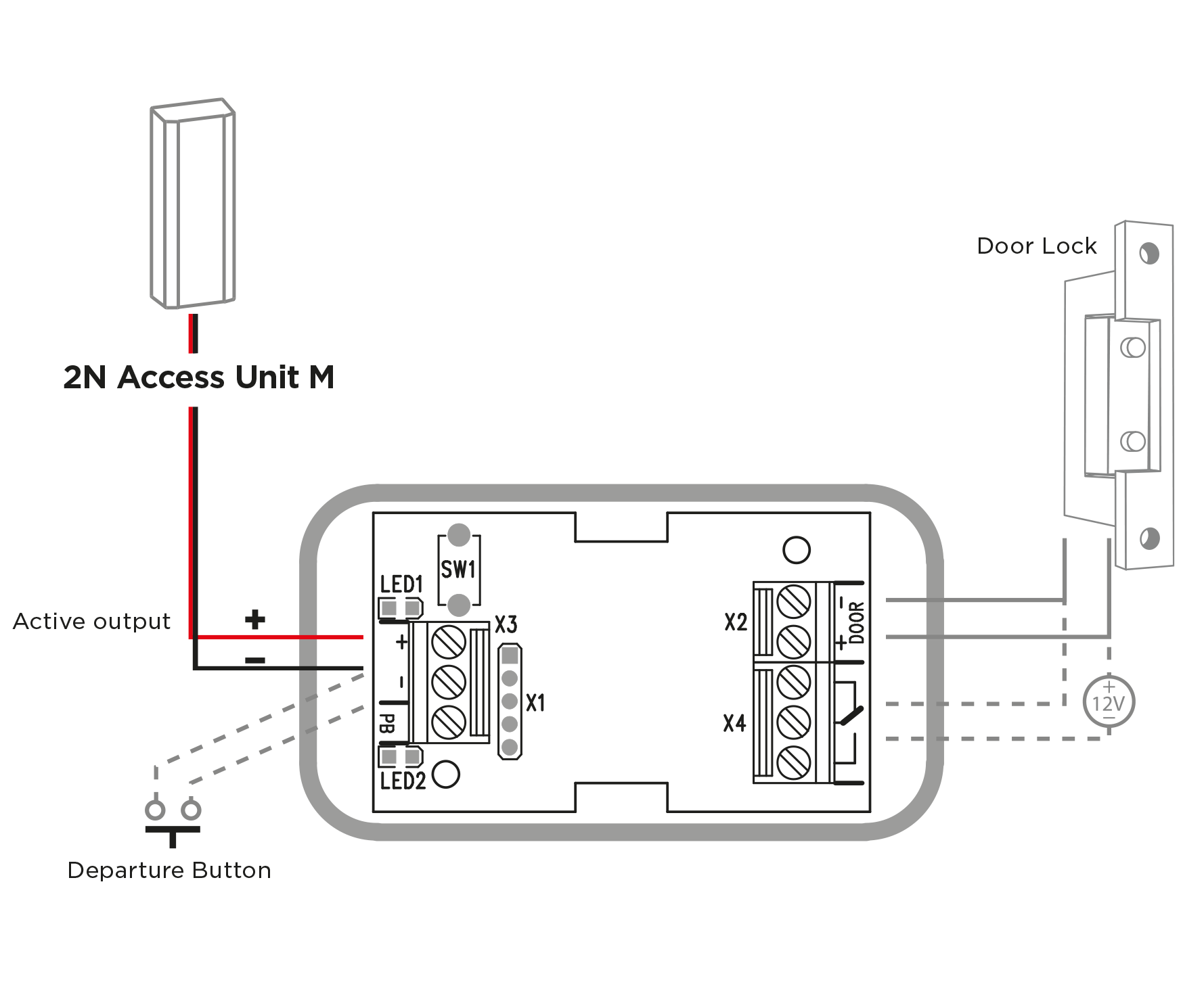
Connection:
Connect the Security Relay to the access unit as follows:
- To the Active output
Connect the electric lock to the Security Relay output as follows:
- To the switched output.
- To the passive output in series with an external power supply.
The device also supports a Departure button connected between the ‘PB’ and – Helios/2N IP intercom’ terminals. Press the Departure button to activate the output for 5 seconds.
Status Signaling:
| Green LED | Red LED | Status |
|---|---|---|
| flashing | off | Operational mode |
| on | off | Activated output |
| flashing | flashing | Programming mode – waiting for initialization |
| on | flashing | Error – wrong code received |
Configuration:
- Connect the Security Relay to the properly set access unit security output. Refer to the 2N Access Unit Configuration Manual. Make sure that one LED at least is on or flashing.
- Press and hold the Security Relay Reset button for 5 seconds to put the device in the programming mode (both the red and green LEDs are blinking).
- Activate the output switch using the keypad, telephone, etc. The first code sent from the intercom will be stored in the memory and considered valid. After code initialization, the Security Relay will pass into the operational mode (the green LED is blinking).
Caution
- In case the factory default values are reset on a device with a firmware version 2.18 or higher, it is necessary to reprogram Security Relay using the instructions above.
Tip
- Video Tutorial: 2N IP Door Intercoms – Security Relay
Connection:
 |