2.3 Electric Installation
2N Access Unit M can be fed either from an external 12 V / 1 A DC power supply or from a PoE 802.3af supporting LAN.
External Power Supply
Use a 12 V ± 15 % SELV supply dimensioned to the current consumption required for the access unit power output to make your device work reliably.
Current consumption [A] | Available power output [W] |
|---|---|
| 1 | 12 |
PoE Supply
2N Access Unit M is compatible with the PoE 802.3af (Class 0–12.95 W) technology and can be supplied directly from the LAN via compatible network elements. If your LAN does not support this technology, insert a PoE injector, Part No. 91378100, between 2N Access Unit M and the nearest network element. This power supply provides
2N Access Unit M with 12 W for its own feeding.
Connection to LAN
2N Access Unit M is connected to the LAN using a UTP/STP cable (category Cat-5e or higher) via the dedicated LAN connector. As the device is equipped with the Auto-MDIX function, you can use both the straight and crossed cable version.
Caution
- We recommend the use of a LAN surge protection.
- We recommend the use of a shielded SSTP Ethernet cable.
Warning
-
This product cannot be connected directly to the telecommunications lines (or public wireless LANs) of any telecommunication carriers (e.g. mobile communications carriers, fixed communications carriers, or internet providers). In the case of connecting this product to the Internet, be sure to connect it via a router.
| Status | Power Consumption [W] | |||||||
|---|---|---|---|---|---|---|---|---|
| 916112 | 9161121 | 916114 | 9161141 | 916115 | 9161151 | 916116 | 9161161 | |
| At relax | 1.6 W | 1.6 W | 1.5 W | 1.5 W | 1.5 W | 1.5 W | 1.5 W | 1.5 W |
| LED – white strip 100 % | 0.12 W | 0.12 W | 0.12 W | 0.12 W | 0.12 W | 0.12 W | 0.12 W | 0.12 W |
| LED – green strip 100 % | 0.15 W | 0.15 W | 0.15 W | 0.15 W | 0.15 W | 0.15 W | 0.15 W | 0.15 W |
| LED – red strip 100 % | 0.20 W | 0.20 W | 0.20 W | 0.20 W | 0.20 W | 0.20 W | 0.20 W | 0.20 W |
| LED – Bluetooth 100 % | – | – | – | – | 0.06 W | 0.06 W | – | – |
| LED – keypad backlight 100 % | – | – | – | – | – | – | 0.15 W | 0.15 W |
| Standard room temperature mode | 0.14 W | 0.14 W | 0.14 W | 0.14 W | 0.14 W | 0.14 W | 0.14 W | 0.14 W |
| OUT1 at maximum possible load | 6 W | 6 W | 6 W | 6 W | 6 W | 6 W | 6 W | 6 W |
| Audio | 0.7 W | 0.7 W | 0.7 W | 0.7 W | 0.7 W | 0.7 W | 0.7 W | 0.7 W |
Description of 2N Access Unit M Cabling
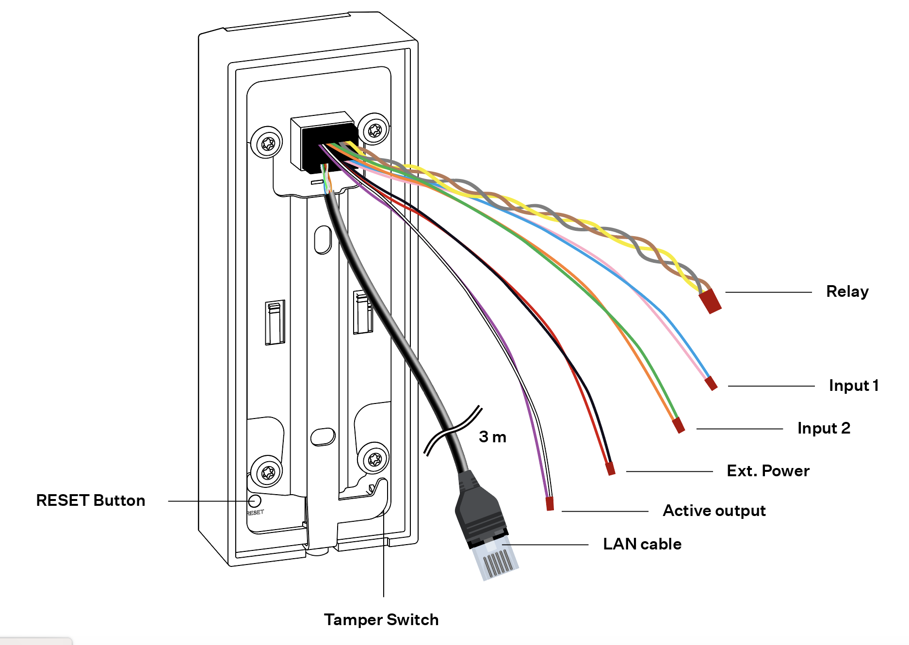
9161121, 9161141, 9161151, 9161161
The LAN cable is 3 m long and terminated with RJ45 male. The other available cables are 35 cm long.
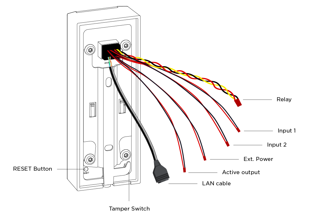
16112, 916114, 916115, 916116
All the available cables are 35 cm long. The LAN cable is terminated with RJ45 female.
| Legend | |
|---|---|
| Relay | Relay cable with a 30 V / 1 A AC/DC NO/NC contact. Used for connection of non-critical devices only (lights, e.g.). |
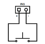
| Input 1, 2 | An input cable used for the connection of a departure button, open door sensor, ESS etc. in the passive/active mode (−30 V to +30 V DC).
|
| Ext. Power | For external power supply connection (12 V / 1 A). |
| Active output | An active output cable for the connection of Security Relay or an electric lock: 8 to 12 V DC according to power supply (PoE: 10 V; adapter: power supply voltage minus 2 V), up to 600 mA. |
| LAN cable | For LAN connection (PoE 802.3af (Class –13.95 W)). |
| Tamper Switch | A switch that helps detect the removal of a device from the holder installed. |
| RESET button | RESET / FACTORY RESET button. |
| Color Designation | |||||
|---|---|---|---|---|---|
| Relay | Input 1 | Input 2 | Ext. Power | Active Output | |
| 9161121, 9161141, 9161151, 9161161 | yellow NO, brown NC, gray COM | pink "+" blue "-" | green "+" orange "-" | red "+" black "−" | white "+" violet "-" |
| 916112, 916114, 916115, 916116 | yellow NO, red NC, black COM | red "+" / black "-" | |||
Cable Joining
The 2N Access Unit M signals are led by insulated wires, which are 1 cm stripped at the ends (excluding the Ethernet cable with a connector). The cables can be joined using any of the below listed methods:
- twisted joint
- terminal block
- soldering
- screw connection
- WAGO terminals
- OOP cap
- crimping using sockets
Tip
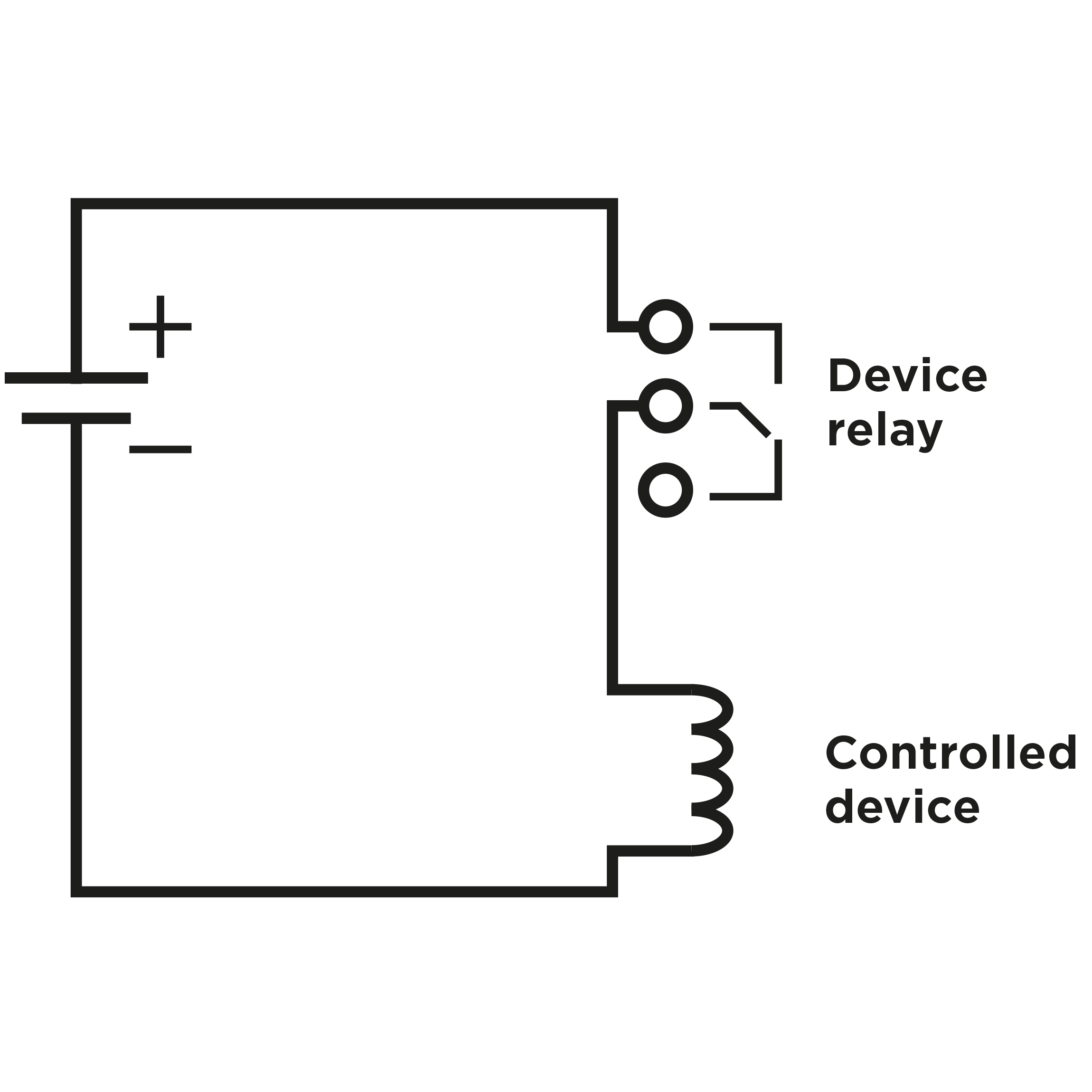
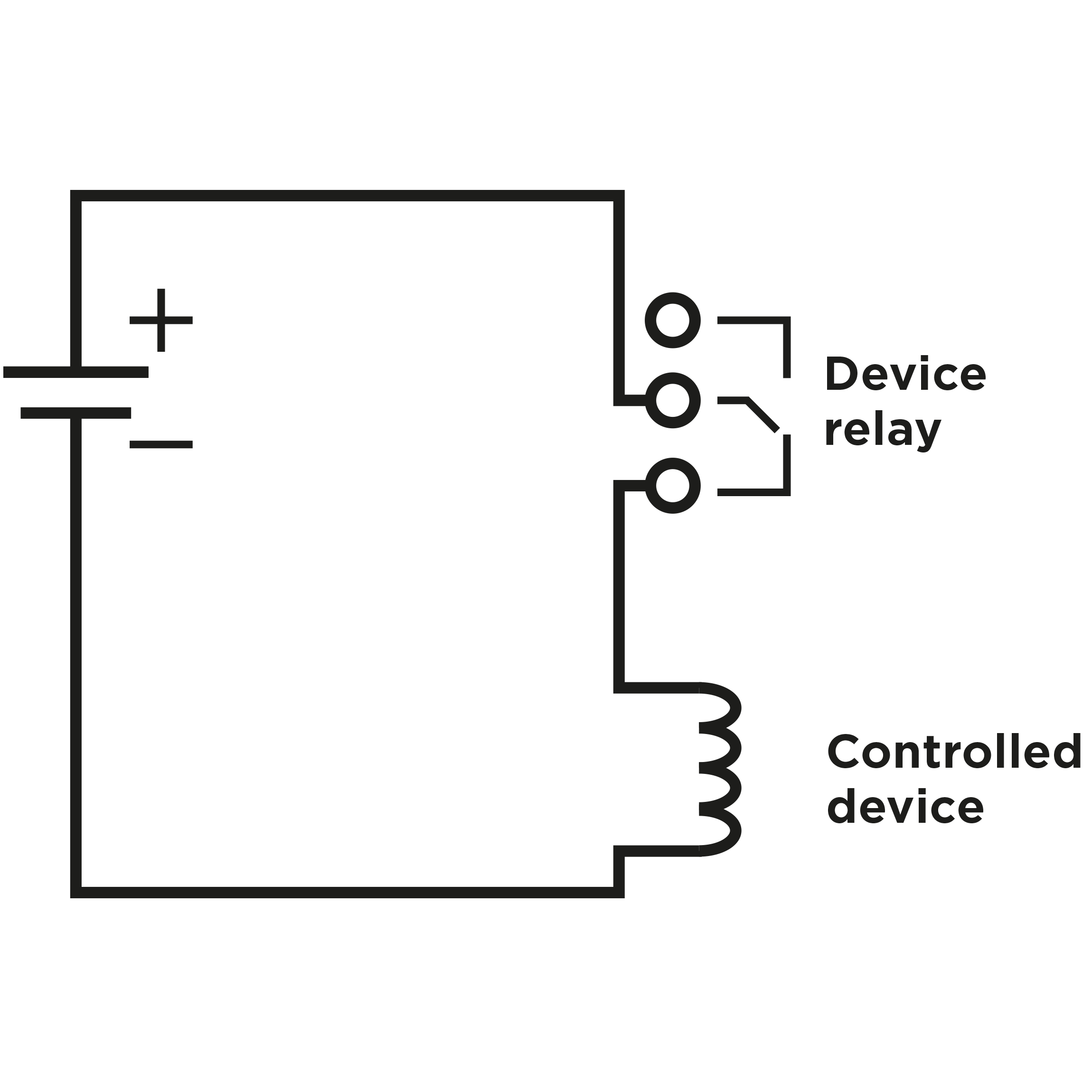
- Output wiring diagram for Relay
Wiring diagram for the controlled device’s electric circuit closing
Wiring Diagram for controlled device’s electric circuit opening
Tip
- Wiring Diagram for IN1, IN2 wires in active mode
- Wiring Diagram for IN1, IN2 wires in passive mode
Security
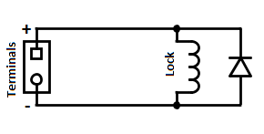
- The 12 V output is used for lock connection. If, however, the unit (2N IP Intercom, 2N Access Unit) is installed where unauthorized tampering may happen (building envelopes), we strongly recommend that Security Relay (Part No. 9159010) be used for enhanced installation security.
Warning
When you connect a device containing a coil, such as a relay or an electromagnetic lock, it is necessary to protect the access system output against voltage peak while switching off the induction load. For this way of protection we recommend a diode 1 A / 1000 V (e.g., 1N4007, 1N5407, 1N5408) connected antiparallel to the device.

