3.3.1 Gateway Control
This group helps:
- Monitor the current statuses of the GSM gateway components;
- Check and set the GSM gateway licence;
- View and save LOG files and CDR.
Firmware / Licence
This window provides information on the gateway licensing, firmware and bootware versions and Ethernet interface MAC address. Use the web interface to download a new licence via Management / Licence.
- Firmware version – current firmware version of the gateway connected.
- Bootware version – current bootware version of the gateway connected.
- Firmware version of VoIP board – current firmware version of the VoIP board connected.
- MAC address – Ethernet interface MAC address of the gateway connected.
- MAC address of VoIP board – Ethernet interface MAC address of the VoIP board connected.
- CPU serial number – GSM gateway serial number in the format M202-xxxxxxxxxx
- Active: licensed protocols:
- SIP – SIP support.
- G729 – G.729ab voice codec support.
- TUN – GSM-CSD remote supervision support.
- DSS1 – ISDN BRI DSS1 protocol support.
- MONI – ISDN monitoring support.
- SMSU – count of SMS users.
- SMSS – SMPP support.
- SMSE – SMS@email support.
- SMSW – SMS via web support.
- SNMP – SNMP monitoring support.
- Gateway limitation – gateway operation time (licence limitation if any).
- Licence status – current licence status (unblocked/blocked).
Caution
- When the licence code expires, the licence–based protocols will be locked!
- Auto licence – current automatic licence status (No/Yes).
Caution
- Auto licence is added via the 2N® SIM Star server.
- If the current Licence status is blocked during automatic licensing, 2N® StarGate will be restarted during licence adding.
- If the current Licence status is unblocked during automatic licensing, the Gateway limitation will be prolonged without 2N® StarGate restart.
- Networks – displays the list of allowed/disallowed GSM/UMTS networks.
Caution
- Upon the dealer's request, the gateway may contain blocking of certain GSM/UMTS networks. This state is indicated by a red shining Ch 1 / Ch 2 LED on the GSM/UMTS board. The GSM module diagnostic window displays the „netw-err‟ status.
- Contact your dealer for more information please.
Date/Time
The Date/Time window enables you to set the current date and time for the gateway. Select the Synchronise with local PC item and the Time and Date items will be set automatically according to your PC data.
Caution
- The internal back-up source is able to back up the internal clock source for a few hours only! Make sure that the gateway date and time values are correct after a long disconnection from the power supply!
Voice Messages
This window is used for recording, checking and downloading voice messages. Supported format is PCM-Alaw, Mono, 8000 Hz, 8 bits.
| Index | Type of message | Use | Max. length(s) |
|---|---|---|---|
| 0 | DISA message | Inc. calls from GSM/UMTS | 64 |
| 21 | GSM outgoing group 1 | Calls via Out. GSM group 1 | 8 |
| 20 | PRI 2 message | Message to PRI 2 in case of deactivated PRI 1 | 16 |
| 22 | GSM outgoing group 2 | Calls via Out. GSM group 2 | 8 |
| 23 | GSM outgoing group 3 | Calls via Out. GSM group 3 | 8 |
| 24 | GSM outgoing group 4 | Calls via Out. GSM group 4 | 8 |
| 25 | GSM outgoing group 5 | Calls via Out. GSM group 5 | 8 |
| 26 | GSM outgoing group 6 | Calls via Out. GSM group 6 | 8 |
| 27 | GSM outgoing group 7 | Calls via Out. GSM group 7 | 8 |
| 28 | GSM outgoing group 8 | Calls via Out. GSM group 8 | 8 |
| 30 | Message 30 | Voice message detector | 8 |
| 31 | Message 31 | Voice message detector | 8 |
| 32 | Message 32 | Voice message detector | 8 |
| 33 | Message 33 | Voice message detector | 8 |
| 34 | Message 34 | Voice message detector | 8 |
| 35 | Message 35 | Voice message detector | 8 |
| 36 | Message 36 | Voice message detector | 8 |
| 37 | Message 37 | Voice message detector | 8 |
You can choose which message will be uploaded or use detection by file name. Detection requires file name: "mess[index of message][optional remark].wav". You can upload more than one message in .tar file.
Note
- The PRI 2 connection message will be played only if the B-channel is opened.
- Voice messages with indexes 30 – 37 are used for detection of the mobile provider's voice message played before call connection. If a match is found of the voice message with any of the voice messages recorded in the gateway, the call is terminated automatically or established via the last GSM outgoing group set in the LCR table (on condition that the ITD – Ignore tone detection in last group parameter is active) in the Gateway Configuration / LCR table section. Refer to the Gateway Configuration / GSM basic parameters / Voice message detector settings for details.
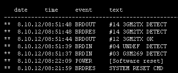
LOG File
The LOG file window helps read out the gateway LOG file. The bottom part of the window includes icons for saving the LOG file into a file and refreshing the LOG listing in the web window.
|
CDR File
The CDR file window helps read out the Call Data Records (CDR) of the gateway. The bottom part of the window includes icons for saving the CDR into a file and refreshing the CDR listing in the web window. Refer to Subs. CDR line description for more details on the CDR format.
Caution
- The maximum capacity is 100,000 call records. When this limit is reached, the oldest record(s) will be deleted automatically!
- The latest 1,000 call records are displayed in the web interface.
- Downloading of a high amount of CDR may take up to several tens of seconds.
SDR File
The SDR file window helps read out the SMS Data Records (SDR) of the gateway. The bottom part of the window includes icons for saving the SDR into a file and refreshing the SDR listing in the web window. Refer to Subs. SDR line description for more details on the SDR format.
Caution
- The maximum capacity is 100,000 SMS records. When this limit is reached, the oldest record(s) will be deleted automatically!
- The latest 1,000 SMS records are displayed in the web interface.
- Downloading of a high amount of SDR may take up to several tens of seconds.
Module Status
This window displays the current status of each GSM/UMTS channel. Refer to the 5.1 List of Status Codes subsection for status details.
Module Control
This window helps you control the selected GSM/UMTS module manually.
- Statuses of layers 2 and 3 – statuses of the module communication layers
- Network name – name of the network where the module is currently logged in
- Network ID – ID number of the network (MCC+MNC) where the module is currently logged in
- Network cell – identification number of the GSM cell the module is currently logged in to.
Displayed code numbers in the A,BBB,CCC,DDDDD format are received from the wireless engine:
A = Status of wireless part:
0 – The wireless engine is currently not registered
1 – The wireless engine is registered to the home network
2 – The wireless engine is not registered, but is searching for a new provider
3 – The wireless engine registration was denied by the network
4 – The unknown reason
5 – The wireless engine is registered to a roaming network
BBB = LAC (Location Area Code) first byte in DEC format; CCC = LAC second byte in DEC format; DDDDD = cell identification code
- Registration to a roaming network is restricted by default. For roaming enable refer to Subs. 3.3.2 Gateway Configuration.
- Upon the dealer's request, 2N can activate the restriction of use for selected wireless networks only. Thus, the gateway will be unable to log in successfully to the restricted wireless networks. This state is signalled by the red status LEDs on the GSM / UMTS cards and the „netw-err‟ message on the configuration tool diagnostics screen.
- Signal – signal level
- Module ID – International Mobile Subscriber Identity (IMSI) or SIM card ID (SCID)
- Module firmware – wireless engine module firmware revision number
- Module IMEI – wireless engine international identification number
- Number of active SIM card positions
Statistics
The window displays the current statistics on calls. The bottom part of the window includes icons for saving the LOG file into a file and refreshing the CDR listing in the web window. Refer to Subs. Statistics for format information.
Current Call Info
The window displays the currently made calls. The bottom part of the window includes icons for saving the LOG file into a file and refreshing the listing in the web window.
Connection State
The window displays the states of all available configuration sessions. The bottom part of the window includes icons for saving the LOG file into a file and refreshing the listing in the web window.
AutoCLIP Routing Table
The window displays the current state of the AutoCLIP table. The bottom part of the window includes icons for saving the LOG file into a file and refreshing the listing in the web window.
Note
- The maximum AutoCLIP routing table capacity is 256 records.
SIP Registration
The window displays the current SIP registration state of the gateway.
Online Report
The window displays on-line gateway tracing.