Loxone mini server - intergration with 2N® intercom
Basic orientation
- Loxone Miniserver (Gen 2) FW Version: v10.3.11.25
- 2N IP Intercom FW: v2.28
Example project file
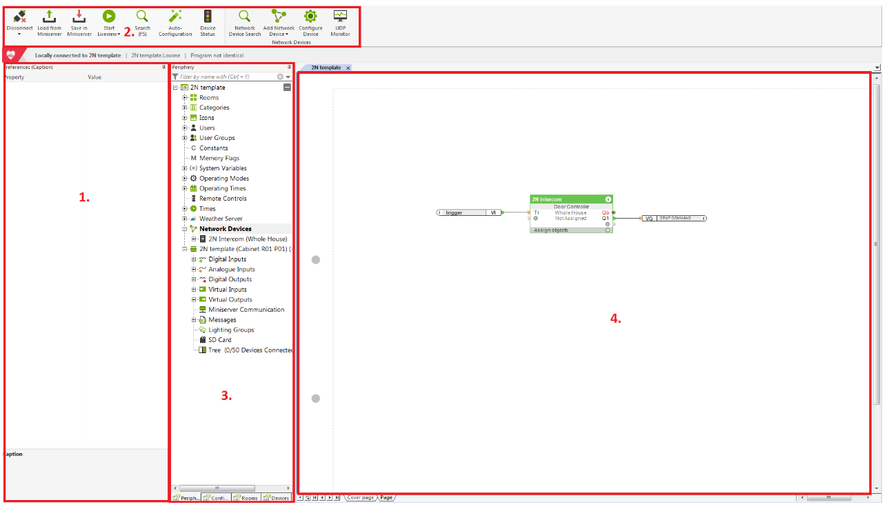
Loxone config tool is divided into a few sections:
- Property menu allows you to define the parameters of a specific object such as name, destinations for http commands etc. The available parameters are different for each object.
- General menu that allows you to assign new objects to the specific periphery section. This menu differs for each periphery.
- Periphery menu that allows you to add specific objects to your project space.
- Project space allows you to place objects from the Periphery menu by using drag and drop method. Interconnection of each object is done here.
Local calls configuration
Loxone Miniserver configuration
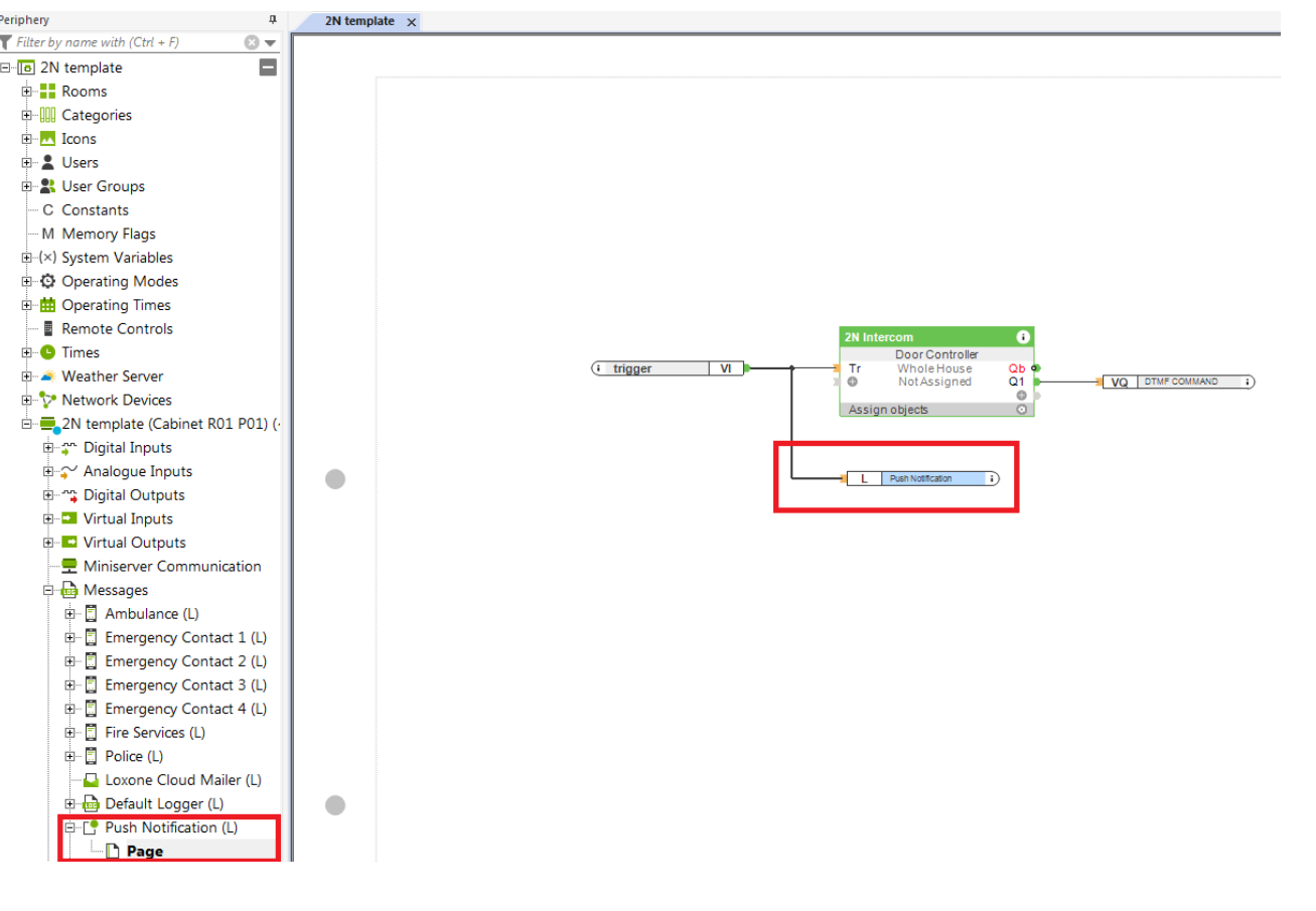
The first step is to let the Loxone mini server know, that the button has been pressed on the intercom side. To be able to achieve it, the http commands will be used. In the Loxone mini server the object called Virtual Input is used. Click on Virtual Inputs in the periphery menu and select Virtual input from the upper general menu. A new virtual input will be created. You can drag and drop this virtual input to your project.

In this example the virtual input is called „trigger“. The name can be assigned to the input in the left property menu by changing the parameter called name (UUID).
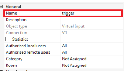
The name of the input is the key parameter here, because it is used in the http command sent from the intercom. Another object which will be use is called „User defined intercom (Door Controller)“. This object can be added to the project by selecting network devices in the Periphery menu and selecting Add Network Device - User defined intercom in the upper general menu.
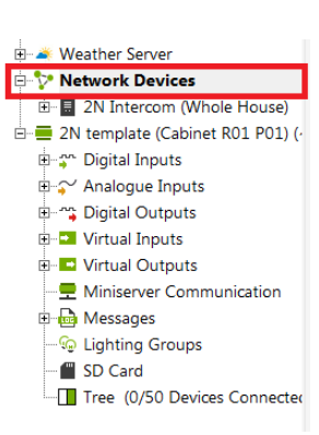
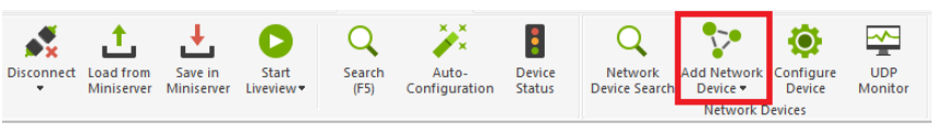
A new Door Controller object will be created in the Network devices. In this example the intercom is called 2N Intercom. The name can be changed again in the left property menu. Now the connection to the intercom needs to be configured. You need to configure the following parameters in the left property menu to be able to make local calls:
- Picture when ringing –the video preview configuration
- URL video stream (local) – the video stream during the call configuration
- User name for Camera – login credentials to access the video from intercom
- Password for Camera - login credentials to access the video from intercom
- Host for audio (local) – destination IP address for the SIP call
Genral intercom’s http API syntax:
- http://<IP address of the intercom>/api/camera/snapshot?width=<value>&height=<value>&fps=<value>
For more info regarding to the HTTP API commands of the intercom click here.
Example of the configuration:
- Picture when ringing – http192.168.50.188/api/camera/snapshot?width=640&height=480&fps=15
- URL video stream (local) - http:// 192.168.50.188/api/camera/snapshot?width=640&height=480&fps=15
- User name for Camera – Admin
- Password for Camera - Admin
- Host for audio (local) – 192.168.50.188
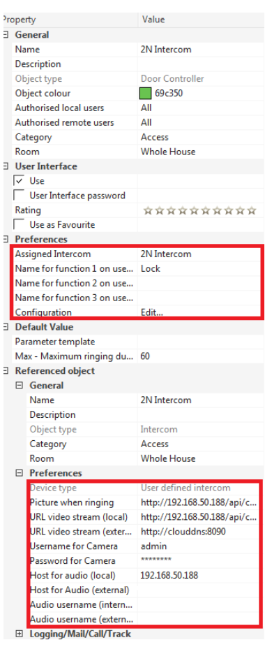
Another parameter that can be configured is called Name for the function 1,2 and 3. This parameter allows you to create a button in the Loxone app which can be used to open the door on the intercom. You can assign the name for the button. In this example the button is called Lock. If the button will be pressed in the app, the specific output on the Door controller object is triggered. These outputs are called Q1, Q2 and Q3 and need to be added to the object.
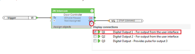
Please note that the doors can be connected directly to the 2N intercom or to Loxone mini server. In this example the lock is directly connected to the intercom, so to be able to open the doors on the intercom, Q1 output needs to be connected to a digital output object called DTMF COMMAND which sends the http command to the intercom. How to configure this object is written in the next paragraph. If the doors are connected to Loxone (Loxone is the one who decides if the doors are open), the Digital Output 1 can be connected to some other object / periphery in the Loxone. This scenario is out of the scope of the guide.
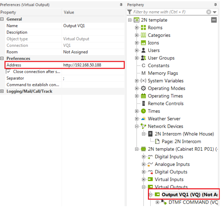
The last step is to add a Virtual Output object which sends an http command to the intercom to open the doors. Select Virtual Outputs in the periphery menu and create a new output by choosing Virtual Output object in the upper menu.


Once the new output is created (in this example VQ1), the virtual output command needs to be assigned from the upper menu and needs to be connected to Q1 output of the Door controller object.

Select the newly created output from the periphery menu (in this example the output is called VQ1) and define the IP address of the intercom in the property menu. In this example the IP address of the intercom is 192.168.50.188.
Select the Virtual output command object from the periphery menu (it is called DTMF COMMAND in this example) and define the http command.

The Http command can control the HTTP API or automation in the intercom. In the example the automation function is used however HTTP API works exactly in the same way just the HTTP command is in a different format. You can check HTTP API manual for more info.
The following command has been used in this example:
- General syntax: http://<ip address of the intercom>/enu/trigger/<key name>
- Example: http://192.168.50.188/enu/trigger/dtmf
key name – is used in the automation on the intercom side as a trigger for some set of actions. In this example the key name is dtmf.
Intercom configuration
On the intercom side, the automation needs to be configured (the enhanced integration license is required).
Once the main quick dial button is pressed, the intercom sends the http command towards the Loxone mini server. The command which controls virtual input has the following format :
General syntax:
<user>:<password>@<IP address of Loxone mini server>/dev/sps/io/<UUID>/<action>
Where
- UUID - name of the virtual input object in Loxone
- Action – on / off commands
Example: admin:admin@192.168.50.182 /dev/sps/io/trigger/on
Login credentials can be changed in the periphery menu, in the section users. You can also create new users and use them instead of the admin access in the HTTP command.
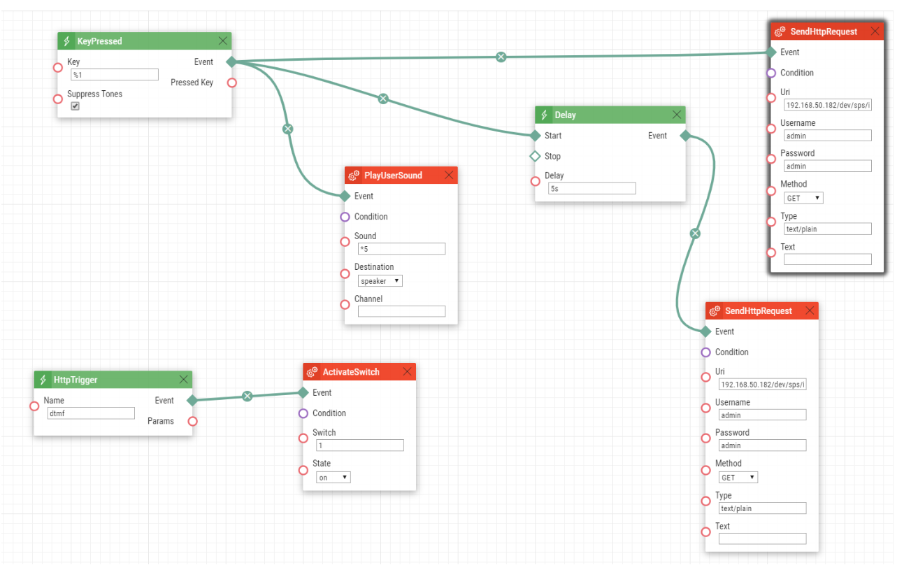
Object SendHttpRequest is sending an HTTP command to the Loxone mini server. Because this object has its own fields for username and password, the URL format is only 192.168.50.182 /dev/sps/io/trigger/on.
The delay object is also triggered during the button press with a 5 second delay and then the intercom sends the http command for the deactivation.
Example: admin:admin@192.168.50.182 /dev/sps/io/trigger/off
Optionally you can also add a PlayUserSound object so once the button will be pressed, the intercom can play some user sound to notify the user in front of the intercom that the intercom is trying to establish the call.
Another object is HttpTrigger where the key for dtmf is used. So once the intercom receives the http command in the format http://192.168.50.188/enu/trigger/dtmf, the intercom activates switch 1.
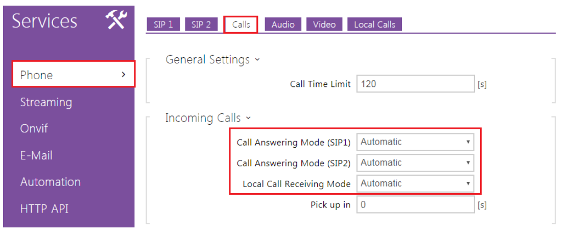
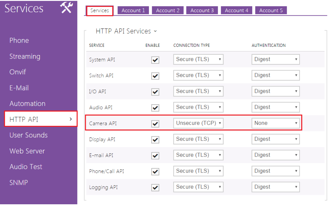
Last step is to set incoming call in the intercom to automatic answering mode in the section Services – Phone - calls and HTTP API access for the video stream.
External calls
To be able to make an external call to the intercom from the Loxone app which is out of your LAN, several configuration adjustments needs to be done:
- Create a SIP account on some free public SIP server which allows you to make anonymous incoming calls and adjust the configuration in the intercom and in the Loxone mini server.
- Register your Loxone mini server
- Setup port forwarding on your router for the Loxone app access and video stream
- Add push notification
The Loxone app / Mini server is always the one who is initializing the SIP call and the calls are anonymous which means that the Loxone mini server is not registered anywhere and trying to establish the peer to peer call.
In case of external calls – only the intercom needs to be registered to the SIP Proxy. Configuration of the door controller is used by the Loxone app on the smartphone and here you only have the options for a SIP host and a user-id. This ID is NOT for the app itself but used to make an anonymous call to the intercom that has been registered as a SIP client with specific credentials. The app is NOT a full SIP client, so it does not register with a SIP provider. The Loxone app can make outgoing calls as an anonymous SIP user to the intercom by using the user-ID as a "phone number" for the destination (the intercom).
SIP account configuration
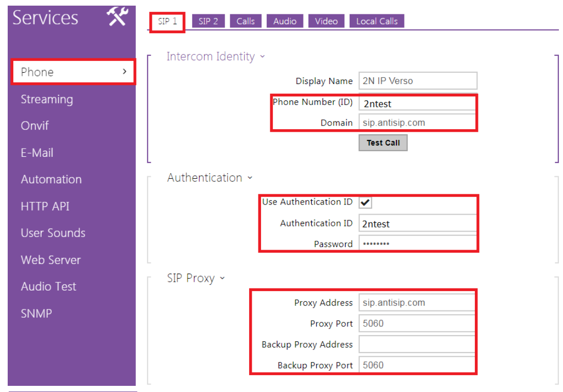
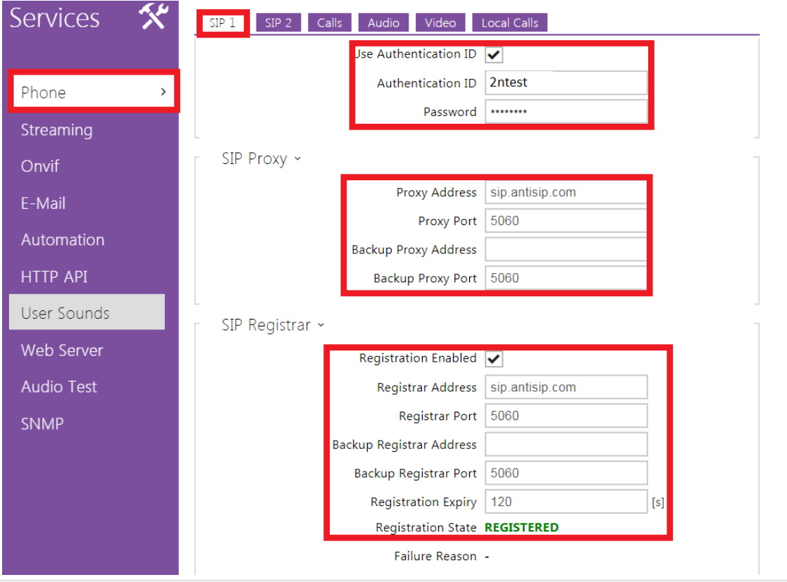
To be able to make an external call, the call needs to be sent to some proxy server which is able to receive calls from unknown sources. In this example server called antisip.com is used. Once the account is created, the intercom needs to be connected to the server. This can be done in section Services – Phone - SIP 1 or SIP 2.
In this example the details obtained from anitsip.com are:

Intercom configuration looks like this:
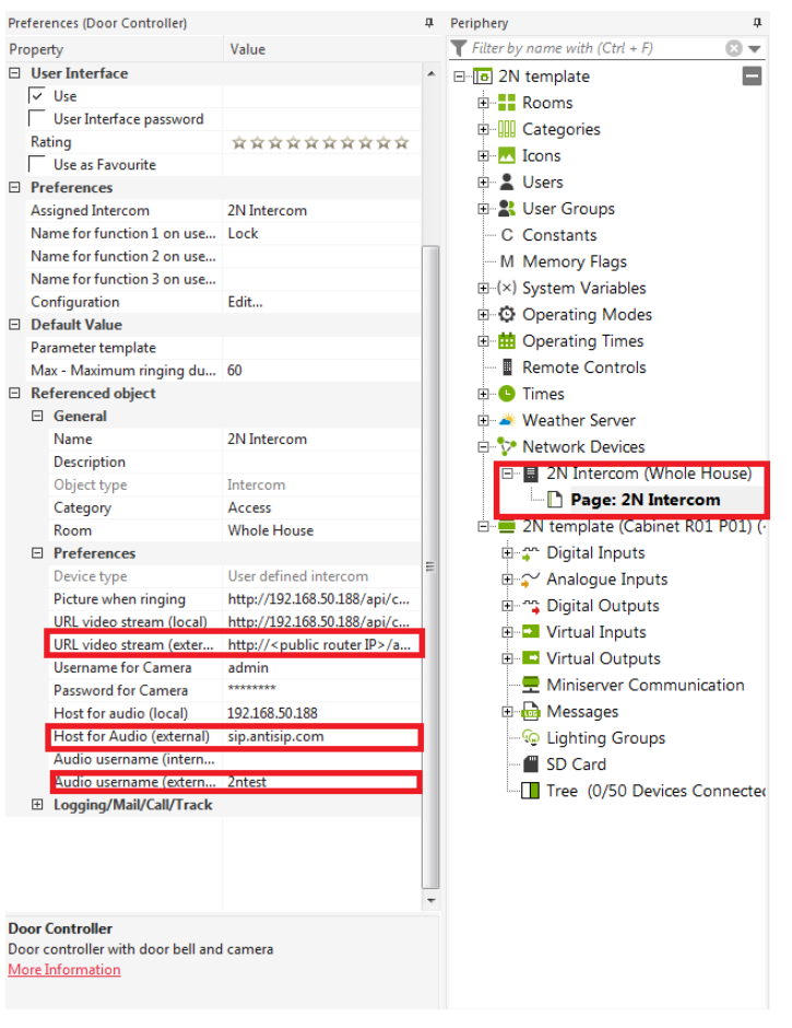
Now the intercom is registered on the antisip.com service and the Door controller settings need to be adjusted to be able to make a call from the mini server to the intercom. In the property menu of the Door Controller the following parameters need to be adjusted:
- Host for audio (external) – the domain name of the service
- Audio username (external) – contact which the Loxone will be calling
- URL video stream (external) - router's public IP address needs to be specified
Port forwarding
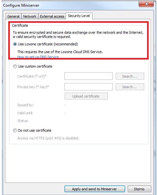
The next step is to create the port forwarding rules in your router to be able to connect from the Loxnone app to the mini server via the internet. Loxone provides a remote connection service. The first step is to register your Loxone mini server on their website. Once the device is registered, the Loxone mini server has a specific domain name to which it is connected. The domain name is dns.loxonecloud.com/<serial number of your server>. The Loxone server detects and stores info about your router public IP address and defined ports (specified in the Loxone mini server configuration - described in the next paragraph) and once the Loxone app, which is placed somewhere in the internet, wants to connect to your mini server which is placed on the LAN, the request is sent to the same domain name and the Loxone DNS server forwards the request to your public IP address with specific port numbers. If the port forwarding rules are done correctly, your router forwards this request to the Loxone miniserver placed on your LAN.
Note that the default password to access the Loxone miniserver cant be used for remote connection. So a password change is required to be able to remotely connect to the Loxone mini server. Password can be changed on the user settings.

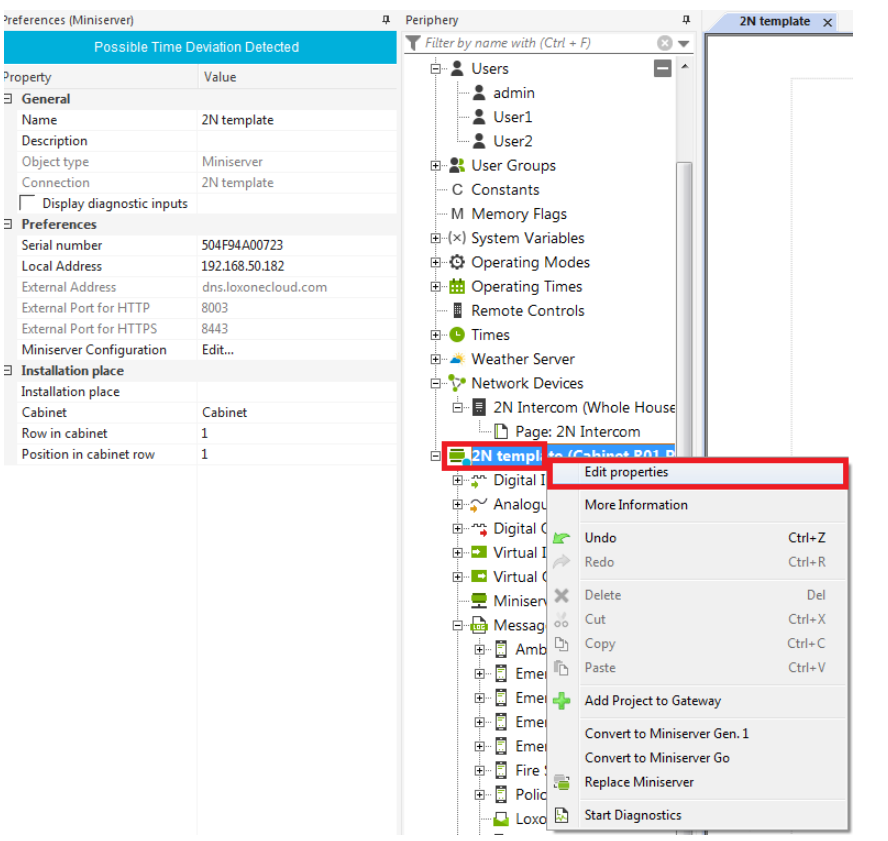
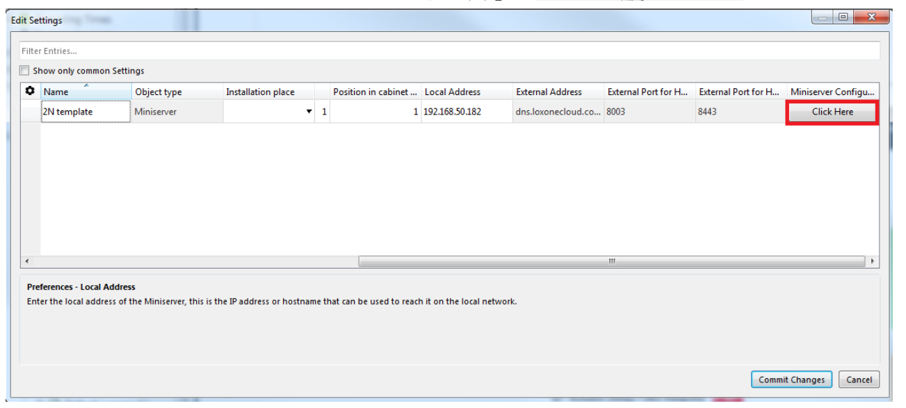
It is necessary to specify which ports will be used for access to the Loxone mini server from the internet. This can be done in the details of the Loxone miniserver. In this example the ports for incoming communication to the Loxone miniserver are 8003 and 8443.
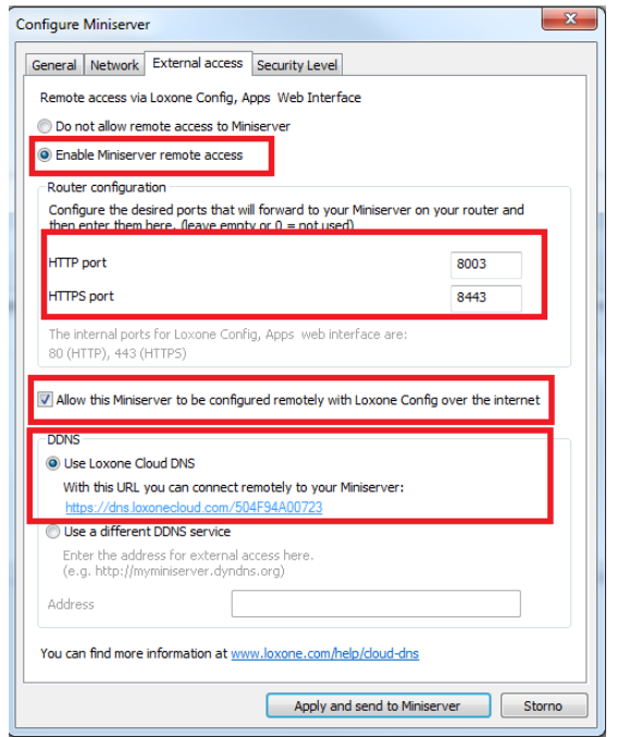
The next step is to configure port forwarding in your router. In this example the router port forwarding details are:
- Incoming traffic to public IP address of the router on port 8003 and 8443 will be forwarded to the IP address of the Loxone miniserver (in this example the ip address is: 192.168.50.182) to ports 80 and 443.
- The port forwarding needs to be specified also for the video stream. In this example again the he port forwarding is done on port 8003 (external) to port 80 (LAN).
The last step is to enable push notification for your smartphone. The push notification mechanism allows you to wake your Loxone app. Each app is closed in IDLE state by the Android / iOS platform and the only mechanism how to wake the app and receive a call is to usethe in built Android / iOS push notification mechanism. Make sure that you have enabled push notifications for the Loxone app. Then add push notification object from Periphery menu into your Loxone project.