Input circuit - 2N® SmartCom/2N® SmartCom PRO calibration
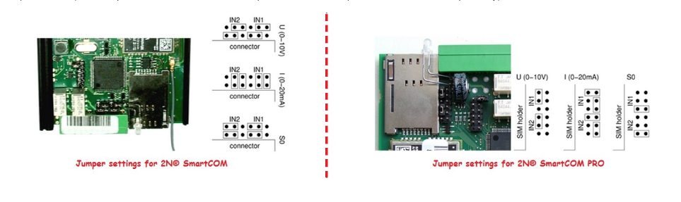
2N® SmartCOM and 2N® SmartCOM PRO terminals are equipped with two inputs which have a common ground (GND). These input circuits can work in three different modes based on the jumper settings – voltage, current or logical levels. The picture below shows the location of jumpers for input switching. For more details you can check user manual for 2N® SmartCOM (PRO) – the link is below:
Note: Voltage mode and current mode will be discussed more deeply in this FAQ because if you want to use them properly then you need to calibrate 10-bits A/D converter connected to the input terminals (IN1 and IN2). But keep in mind that an uncalibrated input is still functional (but can read values less precisely).
Input calibration
The purpose of calibration is to compensate the inaccuracy of components and external factors. It is a reason why you can´t guarantee that the 960 value of the A/D converter matches exactly 10V in each input. The value usually oscillates slightly around this point. Therefore it is recommended to use 10-bits A/D converter that converts the measured value to a number ranging between 0 and 1023. If you want to calibrate inputs then you have to connect to 2N® SmartCOM (PRO) via e.g. Putty and use appropriate AT commands which are described below.
Before we start with the configuration via AT commands let´s take a look on an illustrated diagram where is explained how calibration works and how you can use it.
You can see several different lines in the diagram above and each of them have different meaning. Let´s start with the green one which indicates that no calibration has been made. The A/D converter works in the whole range and deviations may occur from the actual value measured on the input. Now we can set threshold low to 0V and threshold high to 10V on the input and the terminal will be precisely calibrated for 10V. For 0 on the input, the appropriate AT command (mentioned below) will return 0 value. For 10, we obtain 100 from AT command. Thus, the calibrated input can be considered 0 - 100% of the calibrated range.
The red lines mean that the input has been calibrated to the interval of 3 to 8V, i.e. to the range of 5V. This range now represents new measurement limits. If you apply 3V or less on the input, you are in the calibrated min area and the AT command will return 0. If you apply 8V or more, you are in the calibrated max area and the AT command will return 100. This means that the measured range width has narrowed by 50% and 0 - 100% is now mapped to the input range of 3 - 8V.
The blue line is an example of measuring in the calibrated range of 0 to 10V. Once you apply 5V to the input (one half of the calibrated voltage) then AT command will return 50, i.e. one half of the 0 - 100 range again. However if the range was shifted, the value would be shifted too as presented by a yellow line. This line shows the case that 7V is applied to the input. In case you measure 7V in the calibrated 10V range, the AT command will return 70 because it is 70% of the calibrated range. But if the range is just 3 to 8V as in the red case, 7V will represent 80% of the calibrated range of 5V and the AT command will return 80.
How to configure 2N® SmartCOM (PRO)?
- In the very first step (before connecting of load to input circuits) it is necessary to do a calibration of input circuits.
- Set the threshold low value – input circuits has to be shorted and then you have to enter to the command line an AT command for automatic port calibration at^scadc1="calib_min". If you want to set minimum value manually then you have to enter following AT command: at^scadc1="threshold_low",x (where X can be a value from 0 – 960)
- Set the threshold high value – you have to add the load to the maximum threshold line which should not exceed 10V and set to the command line an AT command for automatic port calibration at^scadc1="calib_max". If you want to set maximum value manually then you have to enter following AT command: at^scadc1="threshold_high",x (where X can be again a value from 0 – 960)
- In the last step you have to save calibration by the command: AT^scadc1="save".
- Once you set it and do calibration you can check actual values – use the command at^scadc2?
- All commands mentioned above are also used in the next picture for better illustration and you can read more about them in the user manual – the link is below:
4.2 List of Supported AT Commands
- Finally you can repeat steps above for input 2 (IN2) – you will have to replace command at^scadc1 for at^scadc2. Don´t forget to save the configuration!


Practical usage of the calibration can be e.g. for temperature measurement. If you have thermometer where the temperature is directly proportional to the voltage then you can very easily read out measured values of voltage and trigger some action. Based on these values you are able to decide if you need to cool a room (run fans), if the temperature is in the correct range (fans are off) or if you need to heat the room. The calibration can be done for specific temperature range corresponding to the voltage (let´s say that 28°C = 8V and 10,5°C = 3V). Now you can set that for measured values in the range of 80-100% (24,5°C – 28°C) you need to run a fan or air conditioning. For 40-80% (17,5°C – 24,5°C) are fans off and you don´t need to heat. Finally for 0-40% (10,5 – 17,5°C) you will have to heat in your house. In this case you will have to set threshold high to 8V and threshold low to 3V. Next actions such as relay activation for heating or air conditioning can be triggered based on the actual input value and can be configured such as User Defined Functions (UDF). More information about UDF are available in the manual and next FAQ – links are below:
9. User Defined Functions - UDF
User Defined Functions (UDF) - what is it and how to configure it in 2N® SmartCOM?