Bosch VMS
Content
Bosch Video Management System (BVMS)
About Company:
KEENFINITY – A new era for security and communications technology.
Our journey as an independent company is just beginning, built on decades of expertise in security and communication technology. As a Bosch spin-off (since 2025), we operate in over 90 locations across 50+ countries, delivering state-of-the-art solutions for video surveillance, intrusion detection, access control, and voice alarm systems – all designed to provide security, protect buildings, and assets. Our portfolio also includes professional audio and conference systems, featuring world class brands like Electro-Voice, Dynacord, RTS, and Telex.
About BMVS:
BVMS is a unique IP video security solution that provides seamless management of digital video, audio, and data across any IP network. It provides the best video management system to go with Bosch video surveillance devices, leveraging the unique capabilities of Bosch cameras and recording solutions. It nevertheless offers interfaces and standards to integrate other systems and manufacturers.
Website:
https://www.boschsecurity.com/en/
Key features:
- Reduced total costs of ownership - manage up to 2000 cameras with a single server to reduce installation and operating costs.
- Embedded resilience - keep operations up and running even when multiple system components fail.
- Bosch video at its best - the best user experience combining Bosch cameras with BVMS.
- Integration - integrate third-party cameras, storage and further systems into BVMS.
- IT environments and data security - benefit from full IT compatibility from installation to day-to-day management in a secure way.
Supported features:
Bosch Video Management System | 2N OS FW version | Scan device | Video from 2N IP Intercom | Audio from 2N IP Intercom | Audio to 2N IP Intercom | Switch control | Events from 2N IP Intercom |
13.0.0.292 | 2.49 |
|
|
|
|
|
|
Supported devices:
All 2N IP intercoms with camera support (internal camera or external camera connection capability)
Tested versions:
- BVMS: 13.0.0.292
- 2N OS: 2.49
Required Licenses:
2N Licenses: Gold license
Partner Licences: Consult your BVMS partner
Manual
2N IP Intercom Settings
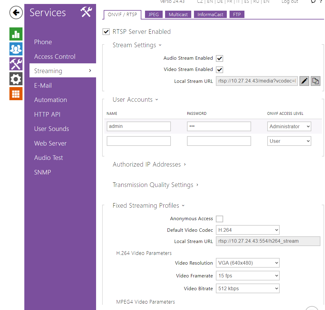
The setting of 2N IP Intercom is very easy. In the first step you have to double check the license uploaded in intercom. Therefore go to section "System – Licence – Licence Status". Next you have to switch to section "Services – Streaming – ONVIF" and enable there RTSP Server and “Audio and Video stream” mode as shown in the picture below.
|
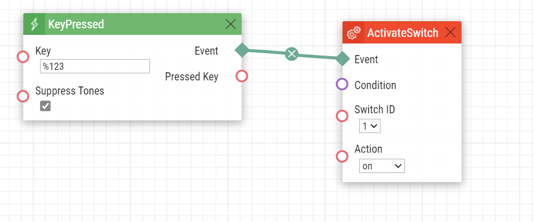
It is now possible to distinguish individual ONVIF Virtual Input Ports, which are identified by the port parameter of the SetOnvifVirtualInput Action block. In the following example Virtual Input Port number 2 is controlled by pressing a quick dial button. It can be of course controlled by different Automation events such as Motion Detected or Input Changed.
 |
If the switch controls are set using automation (see picture below), the relay is no longer set in the Bosch configuration client.
|
|
Settings in the automation of the 2N device - in the Bosch Operator Client, it shows the switch being switched on, for example, after entering a passcode on the keypad when ActivateSwicht is set in automation.
If the Relay is set in the Bosch Configuration Client it is controlled by a state change in the Bosch Operator Client.
BVMS Settings
Go to the Configuration Client, Menu Devices, item Device Tree / VRM Devices / VRM (10.27.55.33) / Pool / Add Streaming Gateway.
 |
Right mouse click at Streaming Gateway, in the context menu choose Scan for ONVIF Encoders. Assign chosen device.
 |
 |
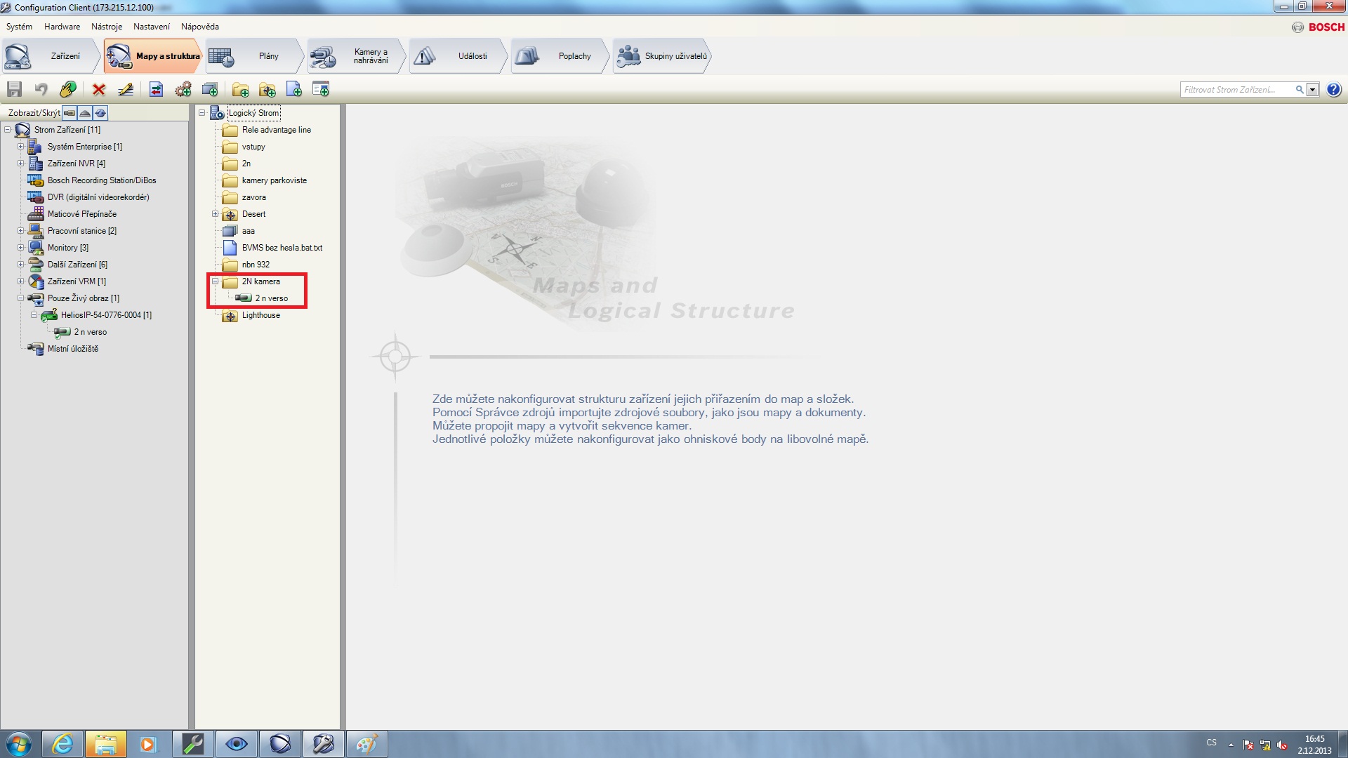
Add 2N IP intercom to the Logical Tree - Drag and drop from Device Tree / VRM Devices / VRM (10.27.55.33) / Pool / Streaming Gateway / Camera 1 (10.27.24.15) to Logical Tree / Cameras.
 |
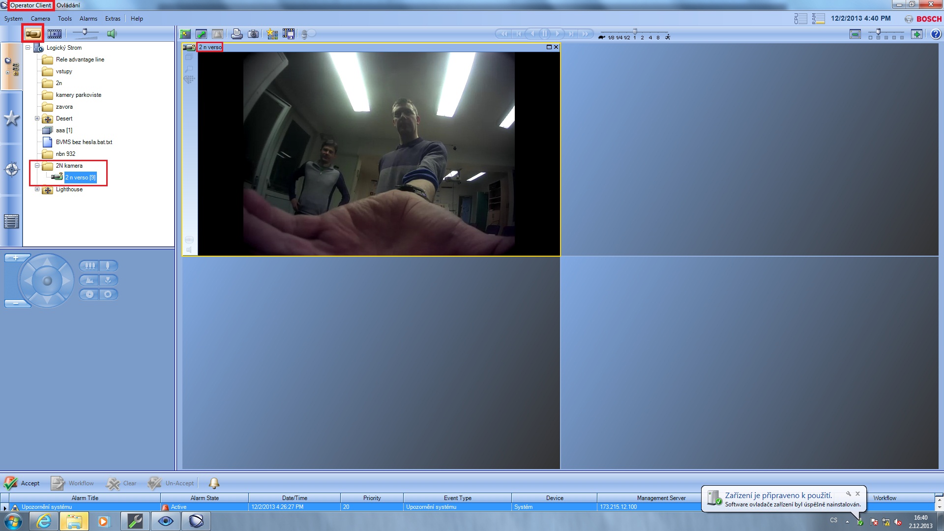
Go to the Operator Client, item Logical Tree / Cameras / Camera 1 (10.0.27.15). Double click opens the camera in a new window. Press the speaker button to turn audio from 2N IP Intercom on.
 |
Go to the Configuration Client, Menu Cameras and Recording, enable Audio in a column Audio.
 |
Go to the Configuration Client, Menu Devices, item Device Tree / VRM Devices / VRM / Pool / Streaming Gateway / 2N-IPVerso[20], Card ONVIF Encoder Events. Events can be managed via Automation as it is demonstrated above. VirtualInput from Automation: Input Opened.
 |
VirtualInput from Automation: Input Closed.
 |
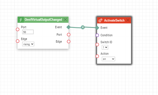
After setting which events correspond to input opening and closing, you can set which ONVIF Virtual Input ports will activate the inputs shown in the left hand side of the screen. Select one of the 10 provided inputs and set it as shown below. The ONVIF Source Value parameter defines which virtual port will activate this input.
 |
If OnvifVirtualOutputChanged is set in automation, the Relay is not set anymore. It is only set if there is, for example, ActivateSwicht in the automation after entering the code.
|

|

|

After setting desired Inputs and Relays add them to the Logical Tree as a Camera was added there before.
|

The difference between setting automation on the 2N device and or setting Relay in the Bosch configuration client is as follows.
Settings in the automation of the 2N device - in the Bosch Operator Client, it shows the switch being switched on, for example, after entering a passcode on the keypad when ActivateSwicht is set in automation.
If the Relay is set in the Bosch configuration client it is controlled by a state change in the Bosch Operator Client.
|

Version 12
Tested Functions
| Bosch Video Management System | 2N IP Intercom Version | Scan device | Video from 2N IP Intercom | Audio from 2N IP Intercom | Audio to 2N IP Intercom | Switch control | Events from 2N IP Intercom |
|---|---|---|---|---|---|---|---|
12.3.0.171 | 2.46 | ||||||
12.1.0.414 | 2.42.1.55.3 |
2N IP Intercom Settings
The setting of 2N IP Intercom is very easy. In the first step you have to double check the license uploaded in intercom. Therefore go to section "System – Licence – Licence Status". Next you have to switch to section "Services – Streaming – ONVIF" and enable there RTSP Server and “Audio and Video stream” mode as shown in the picture below.
|
It is now possible to distinguish individual ONVIF Virtual Input Ports, which are identified by the port parameter of the SetOnvifVirtualInput Action block. In the following example Virtual Input Port number 2 is controlled by pressing a quick dial button. It can be of course controlled by different Automation events such as Motion Detected or Input Changed.
|
If the switch controls are set using automation (see picture below), the relay is no longer set in the Bosch configuration client.
|
|
Settings in the automation of the 2N device - in the Bosch Operator Client, it shows the switch being switched on, for example, after entering a passcode on the keypad when ActivateSwicht is set in automation.
If the Relay is set in the Bosch Configuration Client it is controlled by a state change in the Bosch Operator Client.
Tested Features
Go to the Configuration Client, Menu Devices, item Device Tree / VRM Devices / VRM (10.27.55.33) / Pool / Add Streaming Gateway.
|
Right mouse click at Streaming Gateway, in the context menu choose Scan for ONVIF Encoders. Assign chosen device.
|
|
Add 2N IP intercom to the Logical Tree - Drag and drop from Device Tree / VRM Devices / VRM (10.27.55.33) / Pool / Streaming Gateway / Camera 1 (10.27.24.15) to Logical Tree / Cameras.
|
Go to the Operator Client, item Logical Tree / Cameras / Camera 1 (10.0.27.15). Double click opens the camera in a new window. Press the speaker button to turn audio from 2N IP Intercom on.
|
Go to the Configuration Client, Menu Cameras and Recording, enable Audio in a column Audio.
|
Go to the Configuration Client, Menu Devices, item Device Tree / VRM Devices / VRM / Pool / Streaming Gateway / 2N-IPVerso[20], Card ONVIF Encoder Events. Events can be managed via Automation as it is demonstrated above. VirtualInput from Automation: Input Opened.
|
VirtualInput from Automation: Input Closed.
|
After setting which events correspond to input opening and closing, you can set which ONVIF Virtual Input ports will activate the inputs shown in the left hand side of the screen. Select one of the 10 provided inputs and set it as shown below. The ONVIF Source Value parameter defines which virtual port will activate this input.
|
If OnvifVirtualOutputChanged is set in automation, the Relay is not set anymore. It is only set if there is, for example, ActivateSwicht in the automation after entering the code.
|
|
|
After setting desired Inputs and Relays add them to the Logical Tree as a Camera was added there before.
|
The difference between setting automation on the 2N device and or setting Relay in the Bosch configuration client is as follows.
Settings in the automation of the 2N device - in the Bosch Operator Client, it shows the switch being switched on, for example, after entering a passcode on the keypad when ActivateSwicht is set in automation.
If the Relay is set in the Bosch configuration client it is controlled by a state change in the Bosch Operator Client.
|
Version 10
Tested Functions
| Bosch Video Management System | 2N IP Intercom Version | Scan device | Video from 2N IP Intercom | Audio from 2N IP Intercom | Audio to 2N IP Intercom | Switch control | Events from 2N IP Intercom |
|---|---|---|---|---|---|---|---|
10.0.0.1225 | 2.28.0.37.4 |
2N IP Intercom Settings
The setting of 2N IP Intercom is very easy. In the first step you have to double check the license uploaded in intercom. Therefore go to section "System – Licence – Licence Status". Next you have to switch to section "Services – Streaming – ONVIF" and enable there “WS-Discovery” mode as shown in the picture below.
 |
In the second step you have to enable RTSP stream on 2N IP Intercom. Go to section "Services – Streaming – RTSP" and enable RTSP server. As a last step you have to choose video codec H.264 and enable UDP unicast stream. All these settings are also shown in the picture below.
 |
|
Tested Features
Go to the Configuration Client, Menu Devices, item Device Tree / VRM Devices / VRM (10.27.55.33) / Pool / Add Streaming Gateway.
|
Right mouse click at Streaming Gateway, in the context menu choose Scan for ONVIF Encoders. Assign chosen device.
|
|
Add 2N IP intercom to the Logical Tree - Drag and drop from Device Tree / VRM Devices / VRM (10.27.55.33) / Pool / Streaming Gateway / Camera 1 (10.27.24.15) to Logical Tree / Cameras.
|
Go to the Operator Client, item Logical Tree / Cameras / Camera 1 (10.0.27.15). Double click opens the camera in a new window. Press the speaker button to turn audio from 2N IP Intercom on.
|
Go to the Configuration Client, Menu Cameras and Recording, enable Audio in a column Audio.
|
Go to the Configuration Client, Menu Devices, item Device Tree / VRM Devices / VRM / Pool / Streaming Gateway / 2N-IPVerso[20], Card ONVIF Encoder Events. Events can be managed via Automation as it is demonstrated above. VirtualInput from Automation: Input Opened.
|
VirtualInput from Automation: Input Closed.
|
After setting which events correspond to input opening and closing, you can set which ONVIF Virtual Input ports will activate the inputs shown in the left hand side of the screen. Select one of the 10 provided inputs and set it as shown below. The ONVIF Source Value parameter defines which virtual port will activate this input.
|
|
|
|
|
|
Version 7
Tested Functions
| Bosch Video Management System | 2N IP Intercom Version | Scan device | Video from 2N IP Intercom | Audio from 2N IP Intercom | Audio to 2N IP Intercom | Switch control | Events from 2N IP Intercom |
|---|---|---|---|---|---|---|---|
7.00.223 | 2.19.0.28.5 |
2N IP Intercom Settings
The setting of 2N IP Intercom is very easy. In the first step you have to double check the license uploaded in intercom. Therefore go to section "System – Licence – Licence Status". Next you have to switch to section "Services – Streaming – ONVIF" and set there “Discoverable” mode as shown in the picture below.
 |
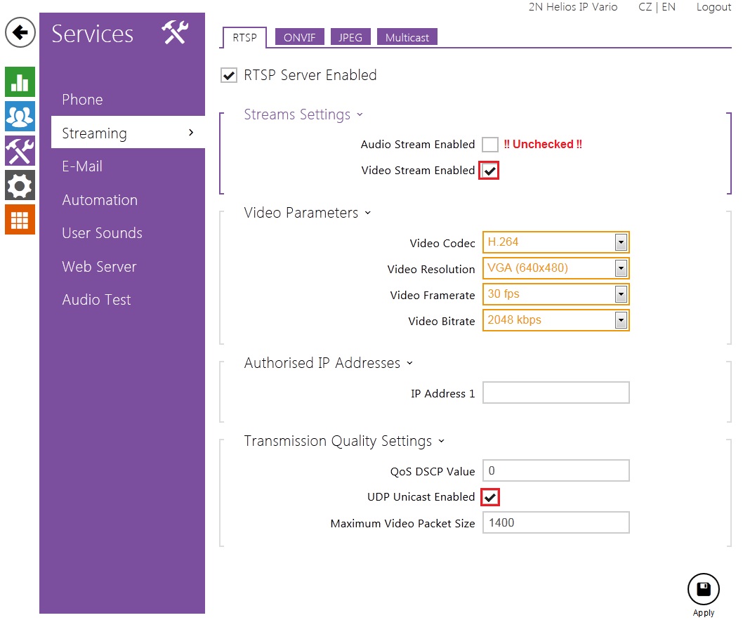
In the second step you have to enable RTSP stream on 2N IP Intercom. Go to section "Services – Streaming – RTSP" and enable RTSP server as well as video stream. As a last step you have to choose video codec H.264 and enable UDP unicast stream. All these settings are also shown in the picture below.
 |
 |
Tested Features
Go to the Configuration Client, Menu Devices, item Device Tree / VRM Devices / VRM (10.0.27.151) / Pool / Streaming Gateway.
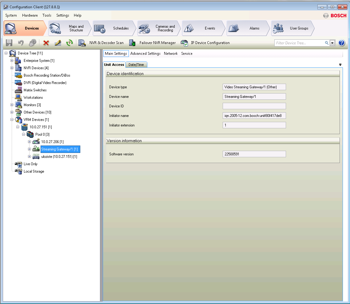 |
Right mouse click at Streaming Gateway, in the context menu choose Add Encoder/camera / ONVIF Encoder.
 |
 |
 |
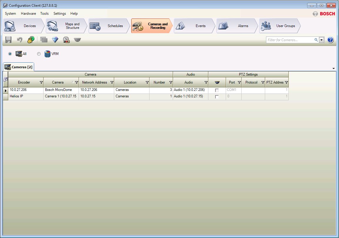
Go to the Configuration Client, Menu Cameras and Recording, enable Audio in a column Audio.
 |
Go to the Configuration Client, Menu Devices, item Device Tree / VRM Devices / VRM / Pool / Streaming Gateway / Helios IP (18), Card ONVIF Encoder Events. Events can be managed via Automation as it is demonstrated above. VirtualInput from Automation: Input Opened.
 |
VirtualInput from Automation: Input Closed.
 |
After setting which events correspond to input opening and closing, you can set which ONVIF Virtual Input ports will activate the inputs shown in the left hand side of the screen. Select one of the 10 provided inputs and set it as shown below. The ONVIF Source Value parameter defines which virtual port will activate this input.
 |
|

|

|

|

|

Version 6
Tested Functions
| Bosch Video Management System | 2N IP Intercom Version | Scan device | Video from 2N IP Intercom | Audio from 2N IP Intercom | Audio to 2N IP Intercom | Switch control | Events from 2N IP Intercom |
|---|---|---|---|---|---|---|---|
6.5.0.325 | 2.17.0.26.1 |
2N IP Intercom Settings
The setting of 2N IP intercom is very easy. In the first step you have to double check the license uploaded in intercom. Therefore go to section "System – Licence – Licence Status". Next you have to switch to section "Services – Streaming – ONVIF" and set there “Discoverable” mode as shown in the picture below.
|
In the second step you have to enable RTSP stream on 2N IP Intercom. Go to section "Services – Streaming – RTSP" and enable RTSP server as well as video stream. As a last step you have to choose video codec H.264 and enable UDP unicast stream. All these settings are also shown in the picture below.
|
 |
Tested Features
Go to the Configuration Client, Menu Devices, item Device Tree / VRM Devices / VRM (10.0.27.151) / Pool / Streaming Gateway.
|
Right mouse click at Streaming Gateway, in the context menu choose Add Encoder/camera / ONVIF Encoder.
|
|
|
Go to the Configuration Client, Menu Cameras and Recording, enable Audio in a column Audio.
|
Go to the Configuration Client, Menu Devices, item Device Tree / VRM Devices / VRM (10.0.27.151) / Pool / Streaming Gateway / Helios IP (18), Card ONVIF Encoder Events. Events can be managed via Automation or directly by defined events at 2N IP Intercom. VirtualInput from Automation: Input Opened.
 |
VirtualInput from Automation: Input Closed.
 |
 |
 |
 |
 |
Version 5
Tested Functions
| Bosch Video Management System | 2N IP Intercom Version | Scan device | Video from 2N IP Intercom | Audio from 2N IP Intercom | Audio to 2N IP Intercom | Switch control | Events from 2N IP Intercom |
|---|---|---|---|---|---|---|---|
5.5.1.515 | 2.12.0.21.4 |
2N IP Intercom Settings
The setting of 2N IP Intercom intercom is very easy. In the first step you have to double check the license uploaded in intercom. Therefore go to section "System – Licence – Licence Status". Next you have to switch to section "Services – Streaming – ONVIF" and set there “Discoverable” mode as shown in the picture below.
|
In the second step you have to enable RTSP stream on 2N IP Intercom. Go to section "Services – Streaming – RTSP" and enable RTSP server as well as video stream. As a last step you have to choose video codec H.264 and enable UDP unicast stream. All these settings are also shown in the picture below.
|
|
Note
- Bosch VMS is not able to distinguish the parameter "port", so only one port can be configured.
Tested Features
Go to the Configuration Client, Menu Devices, item Device Tree / VRM Devices / VRM (10.0.27.151) / Pool / Streaming Gateway.
|
Right mouse click at Streaming Gateway, in the context menu choose Add Encoder/camera / ONVIF Encoder.
 |
|
|
Go to the Configuration Client, Menu Cameras and Recording, enable Audio in a column Audio.
|
Go to the Configuration Client, Menu Devices, item Device Tree / VRM Devices / VRM (10.0.27.151) / Pool / Streaming Gateway / Helios IP (18), Card ONVIF Encoder Events. Events can be managed via Automation or directly by defined events at 2N IP intercom. VirtualInput from Automation: Input Opened.
|
Input Closed
|
Note
- The event KeyReleased is generated immediatelly after the event KeyPressed at 2N® IP Vario.
|
|
Version 4
Tested Functions
| Bosch Video Management System | 2N IP Intercom Version | Scan device | Video from 2N IP Intercom | Audio from 2N IP Intercom | Audio to 2N IP Intercom | Switch control | Events from 2N IP Intercom |
|---|---|---|---|---|---|---|---|
4.5.5 | 2.11.0.20.3 |
2N IP Intercom Settings
 |
In the second step you have to enable RTSP stream on 2N IP Intercom. Go to section "Services – Streaming – RTSP" and enable RTSP server as well as video stream (do not allow audio stream!). As a last step you have to choose video codec H.264 and enable UDP unicast stream. All these settings are also shown in the picture below.
 |
Tested Features
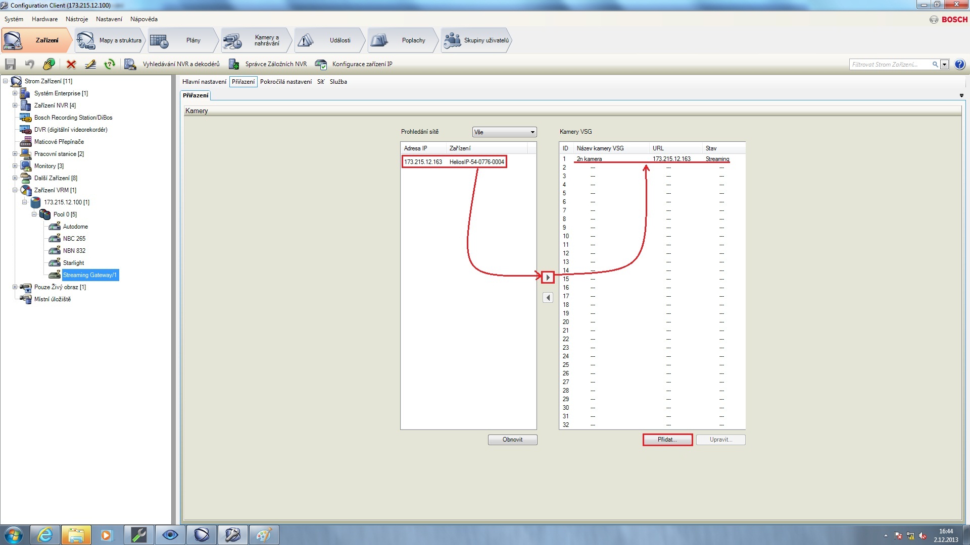
Once you open Bosch software (Configuration Client tool; BVMS version 4.5) go to "Devices" menu on the top bar and select "VRM devices" on the left side of the screen (in our example there was created path "VRM devices – IP_address_of_VRM – Pool – Streaming Gateway") as shown in the picture below. You will see all found IP cameras there and you will have a possibility to modify selected one (IP address of 2N IP Intercom is 173.215.12.163 in our example). Make a double click on this device and fill in username and password (admin : 2n). Click on the “Connect” button after that.
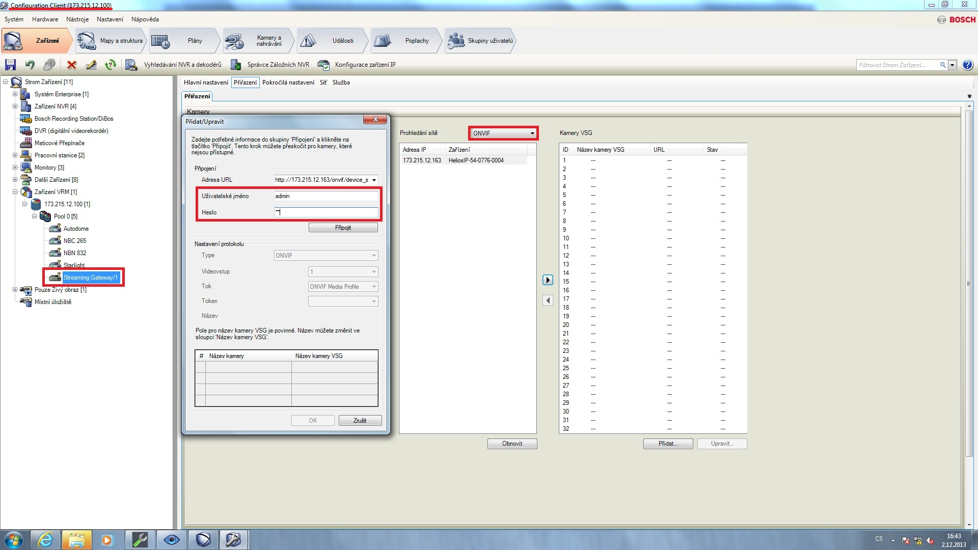 |
Once you press "Connect" button, you will connect to 2N IP Intercom and you will be able to set all necessary parameters for ONVIF protocol. The most important one is “Profile 2” – it is profile for H.264 codec which is used for streaming! Specify also the name of VSG camera. Do not forget to save the settings!
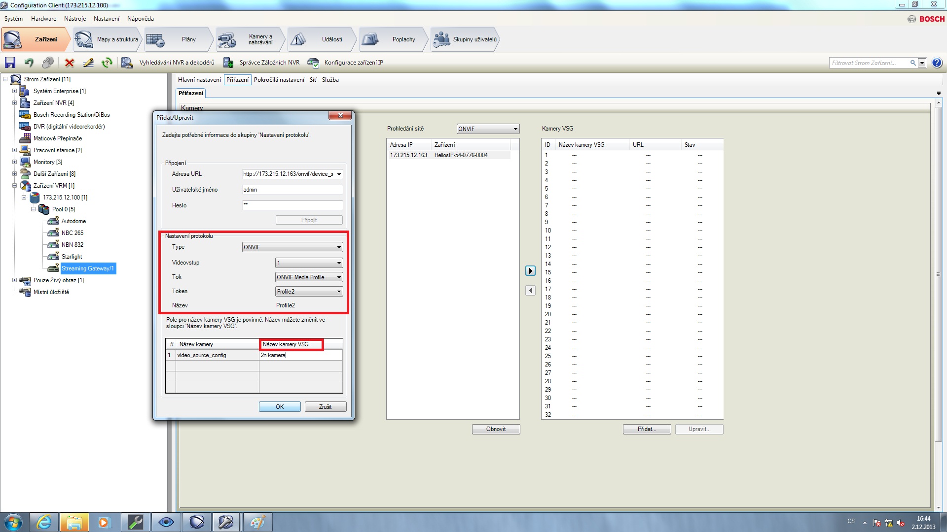 |
 |
 |
 |
Used Symbols
![]() - Compatible
- Compatible
![]() - Work with limitation
- Work with limitation
![]() - Incompatible
- Incompatible