2.4 Extending Module Connection
The 2N IP Style functions can be extended by connecting any of the available 2N IP Verso extending modules via the VBUS connector. Choose the proper accessories for each type of extending module installation.
- 125 kHz RFID card reader
- 13.56 MHz NFC RFID card reader
- Secured 13.56 MHz NFC RFID card reader
- Induction loop
- Fingerprint scanner
- Wiegand module
- OSDP module
- I/O Module
Tamper switch
Caution
- In case the firmware versions of the module to be connected and the main unit are incompatible, the module will not be detected. Therefore, it is necessary to update the device firmware after the modules are connected. Use the device web interface in the System > Maintenance > System configuration section for firmware upgrade (see Configuration manual for 2N IP intercoms).
Module Bus Interconnection
All the extending modules, except for the tamper switch, are interconnected via a bus. The bus starts on the basic unit and goes over all the modules. The order of modules on the bus is irrelevant. And it also irrelevant which bus connector on the module is used as the input and which is used as the output.
The modules include a 220 mm long interconnecting cable, the Wiegand (9155037) and I/O (9155034) modules include an 80 mm long bus cable.
It is possible to order separate bus cables of the length of 1 m, 3 m or 5 m (Part No. 9155050/9155054/9155055 respectively), which are intended for remote module installations. Typically, they help install an RFID card reader on the opposite side of the wall on which 2N IP Style is installed. This cable may only be used once on the bus. The total length of all the bus cables used in these extended installations may not exceed 7 m.
Caution
- Purchase a frame / mounting box for the extending modules to be connected according to the type of installation. This does not apply to the I/O, Wiegand and tamper switch extending modules.
Module Power Supply
All the 2N IP Style modules, except for the tamper switch, are powered from a bus. The available bus power output depends on the power supply type. The basic unit can use a 4A power supply to increase the power available to the modules connected.
| Power supply | Specification | Available power output |
|---|---|---|
| External supply | 12 V ±15 % / 4 A DC | up to 48 |
| PoE+ | 802.3at | up to 21.6 W |
| Combined | External supply + PoE+ |
125 kHz RFID Card Reader Module
The 125 kHz RFID card reader (Part No. 9155032) is one of the 2N IP Verso system elements and is used for reading RFID card IDs in the 125 kHz band.
- The module contains two 2N IP Style bus connectors.
- These two connectors are fully interchangeable and can be used either as inputs from the basic unit or outputs to other modules.
- If this module is the last one on the bus, one of the connectors remains unconnected.
- The module package includes a 220 mm long interconnecting cable.
The following RFID cards can be read:
- EM4xxx
Caution
- We recommend that the M-Bus and LAN cables are not crossed but carried separately through one bushing to increase the reading distance of this reader if combined with a touch display in a single installation.
13.56 MHz RFID Card Reader Module
The 13.56 MHz RFID card reader (Part No. 9155040) is one of the 2N IP Verso system elements and is used for reading RFID card IDs in the 13.56 MHz band.
- The module contains two 2N IP Style bus connectors.
- These two connectors are fully interchangeable and can be used either as inputs from the basic unit or outputs to other modules.
- If this module is the last one on the bus, one of the connectors remains unconnected.
- The module package includes a 220 mm long interconnecting cable.
The following RFID cards can be read:
- ISO14443A (MIFARE DESFire)
- PicoPass (HID iClass)
- FeliCa
- ST SR(IX)
- 2N Mobile Key
Secured 13.56 MHz NFC RFID Card Reader
The 13.56 MHz RFID card reader (Part No. 9155086) is one of the 2N IP Verso system elements and is used for reading secured RFID card IDs in the 13.56 MHz band.
- The module contains two 2N IP Style bus connectors.
- These two connectors are fully interchangeable and can be used either as inputs from the basic unit or outputs to other modules.
- If this module is the last one on the bus, one of the connectors remains unconnected.
- The module package includes a 220 mm long interconnecting cable.
The following RFID cards can be read:
- ISO14443A (MIFARE DESFire)
- PicoPass (HID iClass)
- FeliCa
- ST SR(IX)
- 2N Mobile Key
- HID SE (Seos, iClass SE, MIFARE SE)
Induction Loop Module
The Induction loop module (Part No. 9155041) is one of the 2N IP Verso system elements and is used form transmitting audio signals directly into a hearing aid via a magnetic field.
- The module contains two 2N IP Style bus connectors.
- These two connectors are fully interchangeable and can be used either as inputs from the basic unit or outputs to other modules.
- If this module is the last one on the bus, one of the connectors remains unconnected.
- The module package includes a 220 mm long interconnecting cable.
- Used mode: T
- Maximum power: 2 W
- Frequency range: 100 Hz – 5 kHz / ± 3 dB
- External antenna (Part No. 9155043) connection option
- Antenna output short circuit resistance: without limitation
Fingerprint Reader Module
The Fingerprint reader (Part No. 9155045) is one of the 2N IP Verso system elements and is used for verification of human fingerprints for access control and intercom / third party equipment control.
- The module contains two 2N IP Style bus connectors.
- These two connectors are fully interchangeable and can be used either as inputs from the basic unit or outputs to other modules.
- If this module is the last one on the bus, one of the connectors remains unconnected.
- The module package includes a 220 mm long interconnecting cable.
Important module properties:
- FBI PIV and Mobile ID certification – FAP20
- Durable glass touch surface
- Rejection of spoof fingerprints
- Operating temperature range: −20 to 55 ºC
- 0–90 % relative humidity, noncondensing
Warning
- The fingerprint reader is not intended for direct sunlight installation sites. Installation at such places may result in erroneous behavior.
Caution
- A higher moisture may deteriorate the finger papillary line scanning. You are advised to dry your finger and the reader scanning surface for successful authentication.
- Fingerprint scanning may be more difficult for seniors whose finger papillary lines are not so distinctive (skin elasticity drops with age and a higher scanning pressure may lead to fingerprint blurring).
Wiegand Module
The Wiegand module (Part No. 9155037) is one of the 2N IP Verso system elements and is used for connecting an external Wiegand device (RFID card reader, fingerprint / biometric data scanner) and/or connecting the intercom to an external security exchange. All the inputs and outputs are galvanically isolated from the intercom with the insulation strength of 500 V DC. It is necessary to feed +U IN on Wiegand OUT from the Control Panel.
- Reader – connects an external Wiegand-supporting reader. The reader sends information on the intercom card number.
- Control Panel – used for connection to the security PBX / access system to which the intercom sends the card number information.
- The module contains two 2N IP Style bus connectors.
- These two connectors are fully interchangeable and can be used either as inputs from the basic unit or outputs to other modules.
- If this module is the last one on the bus, one of the connectors remains unconnected.
- The module package includes a 80 mm long interconnecting cable.
Configure the module name in the Module name parameter in the Hardware / Extending modules menu.
The LED IN input is addressed as follows: <module_name>.<input1>, e.g. module2.input1.
The Tamper input is addressed as follows: <module_name>.<tamper>, e.g. module2.tamper.
The LED OUT output (negated) is addressed as follows: <module_name>.<output1>, e.g. module2.output1.
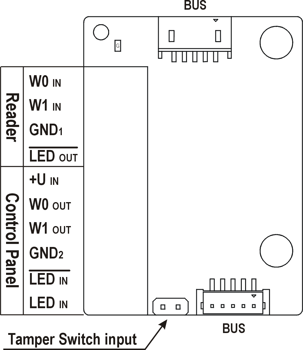 |
| Reader | W0 | Isolated 2-wire WIEGAND IN |
LED | Isolated open LED OUT switched against GND | |
| Control Panel | +U IN | +U input (5 to 15 V DC) for WIEGAND OUT power supply |
W0 OUT, W1 GND2 | Isolated 2-wire WIEGAND OUT | |
LED IN (negated) | Isolated input for open LED IN, input activated by GND2 connection | |
LED IN | Isolated input for open LED IN, input activated by +U connection | |
| G | +U | |
| TAMPER | Tamper switch (Part No. 9155038) input |
| Technical Parameters of Wiegand Input | |
|---|---|
| Current | 5 mA |
| Input resistance | 680 Ohm |
| Pulse length | 50 μs |
| Inter-pulse interval | approx. 2 ms |
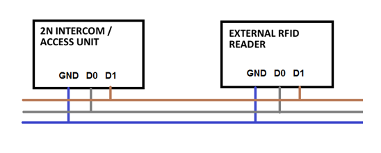 |
Recommended reader - bus driver wiring diagram
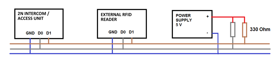 |
Recommended reader wiring diagram with OC output
OSDP Module
The OSDP module (Part No. 91550371) is one of the 2N IP Verso modules and provides communication between a connected device (control panel, door controller) and 2N IP Intercom via the OSDP. The OSDP module provides secure sending of such access data as the access card ID or PIN code. All the inputs and outputs are galvanically isolated from the 2N IP Intercom system with insulation strength of 500 V DC.
- The module contains two VBUS connectors for device bus connection.
- These two connectors are interchangeable and can be used either as inputs from the basic unit or outputs to other modules.
- If this module is the last one on the bus, one of the connectors remains unconnected.
- The module package includes a 80 mm long interconnecting cable.
The module also includes:
- Isolated OSDP bus
- Power and pairing mode signaling LED
- Tamper switch (9155038) input
 |
Having connected the OSDP module to 2N IP Style via the VBUS, connect the OSDP device to the module. The OSDP module uses the RS-485 bus for the interface.
Connect the OSDP device as instructed (A to B or B to A) keeping the correct order to avoid malfunction.
Caution
- When the JP2 and JP3 jumpers are mounted, strong pull-up / pull-down resistors (560 ohm) are connected to the RS-485 bus. These jumpers must be mounted / unmounted together, i.e. you cannot mount just one of them. The strong pull-up / pull-down resistors can be connected only and exclusively to one arbitrary device on the OSDP bus.
- When the JP4 jumper is mounted, a 120 ohm termination resistor is placed between the A and B wires of the OSDP bus. The termination resistors can be connected exclusively to the first and last OSDP bus modules. We recommend that these resistors are connected to the first and last modules.
Having logged in to the 2N IP Style web interface, use the HW / Extending Modules menu to set the following:
- Give the module a user identification (optional).
- Choose a group for access data resending, making sure that the settings are identical with those of the access readers from which the data are to be resent (card ID< PIN).
- The settings of the codes to be transmitted are optional.
- Enter the OSDP address between 0 and 126 to set the OSDP module address on the OSDP line.
- Set the communication rate in accordance with the requirements of the device to be connected.
- Enter your own encryption key into 2N IP Style and the opponent’s device to ensure encrypted communication.
- Enable forced encryption just for encrypted communication.
Any unencrypted communication from the OSDP device will be rejected if forced encryption is enabled.
If the OSDP device enables remote encryption key setting on a peripheral, you can use the installation mode. Once the encryption key is received, the common mode is automatically switched on. The installation mode is signaled by a LED fast blinking on the OSDP module.
I/O Module
The I/O module (Part No. 9155034) is one of the 2N IP Verso intercom elements and is used for extending the number of inputs and outputs.
- The module contains two 2N IP Style bus connectors.
- These two connectors are fully interchangeable and can be used both as inputs from the main unit and outputs to other modules.
- If this module is the last one on the bus, one of the connectors remains unconnected.
- The module package includes an 80 mm long interconnecting cable.
The inputs / outputs are addressed as follows: <module_name>.<input/output_name>, e.g. module5.relay1. The module name is configured in the Module name parameter in the Hardware / Extenders menu.
RELAY1 | RELAY1 terminals with accessible 30 V / 1 A AC/DC NO/NC contact |
RELAY2 | RELAY2 terminals with accessible 30 V / 1 A AC/DC NO/NC contact |
IN1 | IN1 terminals for input in passive/ active mode (−30 V to +30 V DC) OFF = open OR UIN > 1.5 V ON = closed contact OR UIN < 1.5 V |
IN2 | IN2 terminals for input in passive/active mode (−30 V to +30 V DC) OFF = open OR UIN > 1.5 V ON = closed contact OR UIN < 1.5 V |
| TAMPER | Tamper switch (9155038) input |
Tamper Switch Module
The Tamper switch module (Part No. 9155038) is one of the 2N IP Verso system elements and helps secure the system against tampering.
- The module contains two switches, which open whenever the front frame is removed:
- One switch leads directly to the terminal board and is connected to an external security exchange (32 V DC / 50 mA max).
- In coordination with the I/O module (9155034) or Wiegand module (9155037), the other switch can be used for initiating alarm via the Automation interface in the 2N IP Style configuration.
- This module is not connected to the bus.
Caution
- Remember to purchase the I/O module, Part No. 9155034, along with the tamper switch.