2.3 Electric Installation
This subsection describes how to connect 2N® IP Uni into your Local Area Network (LAN) and how to connect supply voltage and the electric lock.
Caution
- The device must be part of the electrical system of the building.
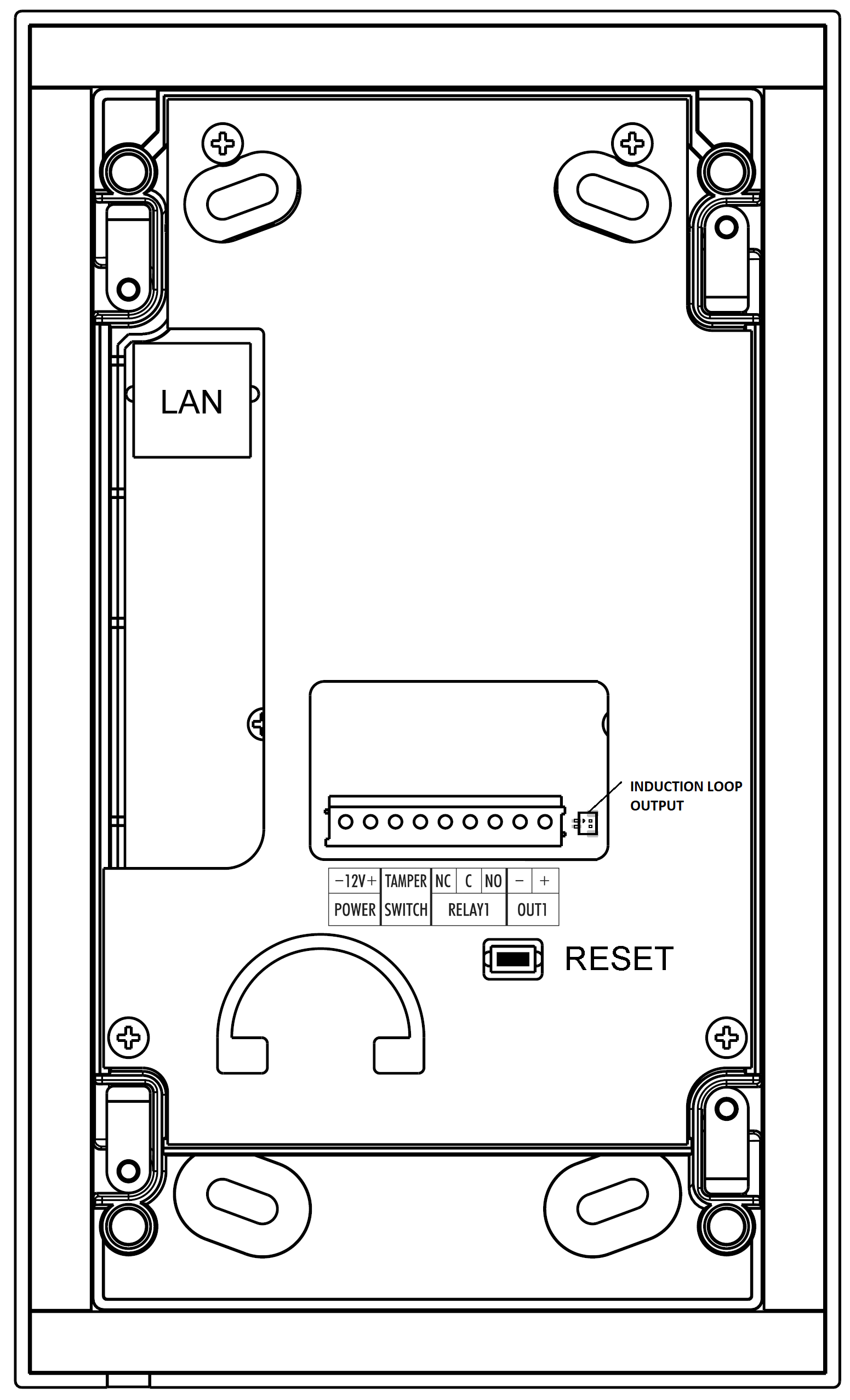
PCB Connectors
Description of Connectors
- LAN – LAN connector
- OUT1 – Active switched output
- RELAY1 – Relay NO/NC contacts. Used for connection of non-critical devices only (lights, e.g.).
- TAMPER – Tamper switch
- POWER – Power input
- RESET – RESET button
- INDUCTION LOOP OUTPUT – Output for 2N® Induction Loop. Connector type JST SHR-02V-S.
 |
LAN Connection
2N® IP Uni is connected to the LAN via a RJ-45 terminated (connector LAN) UTP/STP cable (of category Cat 5e or higher). The system is equipped with the Auto-MDIX function and so both the straight and crossed cable versions can be used
Caution
- We recommend the use of a LAN surge protection.
- We recommend the use of a shielded SSTP Ethernet cable.
External Power Supply Connection
2N® IP Uni can be fed either from an external 12 V / 2 A DC power supply or from the LAN equipped with the PoE 802.3af supporting network elements.
External Power Supply
An external 12 V power supply is connected to terminal block POWER. Use a 12 V ±15 % DC power source dimensioned to current intake of 2 A at least (Part No. 91341481E) to ensure a reliable function of your device.
PoE Supply
2N® IP Uni is compatible with the PoE 802.3af (Class 0 – 12,95 W) technology and can be supplied directly from the LAN via compatible network elements. If your LAN in incompatible, insert the PoE injector, Part No. 91378100E/US, between
2N® IP Uni and the nearest network element.
Electric Lock Connection
2N® IP Uni is equipped with active switched output 8 up to 12 V DC depending on power supply (PoE: 9 V; adaptor: power supply voltage minus 2 V), max 600 mA, switched output (terminal block OUT1), to which a standard electric lock or another compatible electrical appliance can be connected.
Tip
- Output wiring diagram for Relay terminals
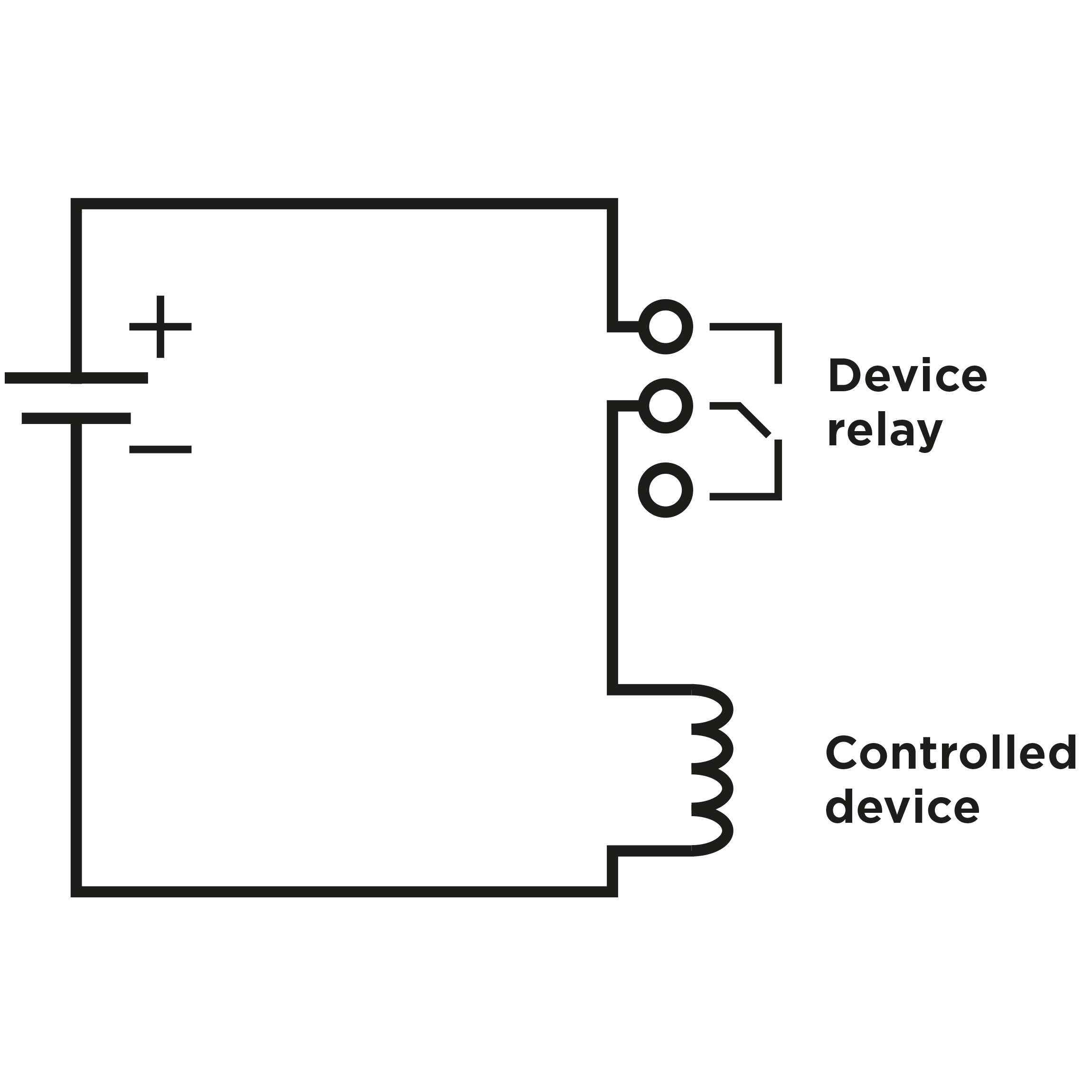 |
Wiring diagram for the controlled device’s electric circuit closing
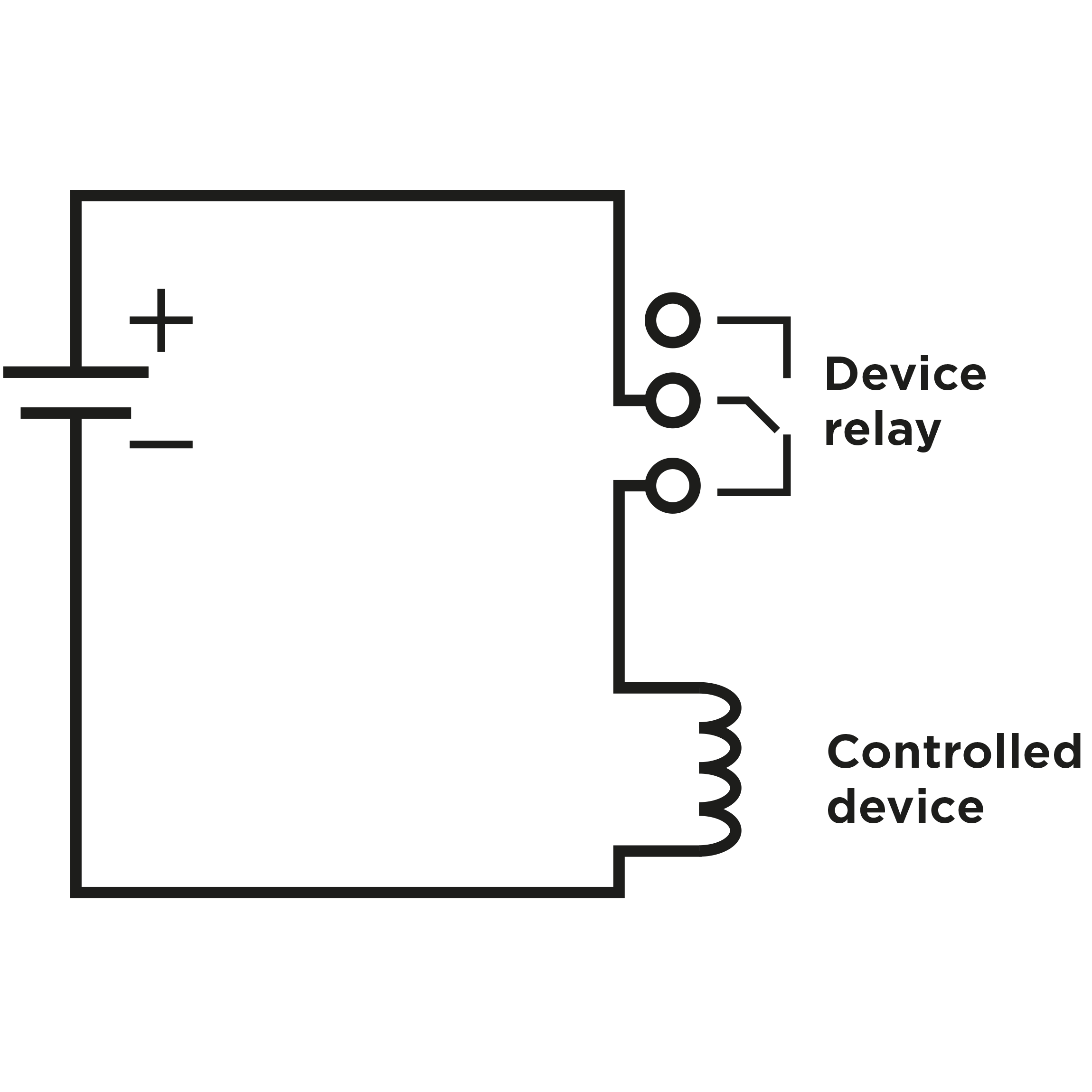 |
Wiring diagram for the controlled device’s electric circuit opening
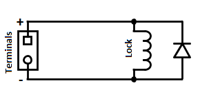
Warning
When you connect a device containing a coil, such as a relay or an electromagnetic lock, it is necessary to protect the intercom against voltage peak while switching off the induction load. For this way of protection we recommend a diode 1A / 1000V (e.g., 1N4007, 1N5407, 1N5408) connected antiparallel to the device.
 |
Note
- Both outputs OUT1 and RELAY1 are switched always simultaneously.
Tamper Switch Connection
2N® IP Uni is equipped with a tamper switch for detection of unauthorized penetration into the device. After correct and complete installation of the device the tamper switch is closed. Tamper switch opens immediately when the front panel is removed. Tamper switch contacts are available on terminal block TAMPER SWITCH.
Device Resetting
2N® IP Uni is equipped with a RESET button. Push the button for 30 s to reset the factory default values, deleting all the data stored in the device.
Caution
- In case of resetting the factory default settings on a device with a version of firmware 2.18 or higher it is necessary to reprogram the
2N® Security Relay using the instructions from section 2.5 Extending Module Connection.
Device Restarting
Press the RESET button shortly (< 1 s) to restart the system without changing configuration.
Note
- The time interval between the short press of RESET and reconnection after restart is 30 s for 2N® IP UNI.