2.5 Extending Module Connection
2N IP Uni allows to connect following extending modules:
Caution
- In case the firmware versions of the module to be connected and the main unit are incompatible, the module will not be detected. Therefore, it is necessary to update the device firmware after the modules are connected. Use the device web interface in the System > Maintenance > System configuration section for firmware upgrade (see Configuration manual for 2N IP intercoms).
Security Relay
The 2N Security Relay (Part No. 9159010) is used for enhancing security between the intercom and the connected electric lock. The 2NSecurity Relay is designed for any 2N IP intercom model with firmware versions 1.15 and higher. It significantly enhances security of the connected electric lock as it prevents lock opening by forced intercom tampering.
 |
Function:
The 2N Security Relay is a device installed between an intercom (outside the secured area) and the electric lock (inside the secured area). The 2N Security Relay includes a relay that can only be activated if the valid opening code is received from the intercom.
Specifications:
Passive switch: NO and NC contacts, up to 30 V / 1 A AC/DC
Switched output:
- Where the security relay is fed from the intercom, 9 to 13 V DC is available on the output depending on the power supply (PoE: 9 V; adapter: source voltage of minus 1 V) / 400 mA DC.
- Where the security relay is fed from an external power supply, 12 V / 700 mA DC is available on the output.
Dimensions: 66.5 x 32.5 x 20.5 mm
Weight: 24 g
Installation:
Install the 2N Security Relay onto a two-wire cable between the intercom and the electric lock inside the area to be secured (typically behind the door). The device is powered and controlled via this two-wire cable and so can be added to an existing installation. Thanks to its compact dimensions, the device can be installed into a standard mounting box.
The Security relay is designed with holes for surface anchoring. It is recommended that a screw of the diameter of 3 mm with a lens head of the diameter of 6 mm is used. Using a countersunk head may cause irreversible damage to the plastic cover!
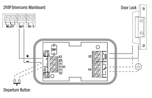
Connection:
Connect the 2N Security Relay to the intercom as follows:
- To the intercom active output (OUT1)
Connect the electric lock to the 2N Security Relay output as follows:
- To the switched output.
- To the passive output in series with the external power supply.
The device also supports a Departure button connected between the ‘PB’ and ‘- HeliosIP/IP Intercom’ terminals. Press the Departure button to activate the output for 5 seconds.
Status signalling:
| Green LED | Red LED | Status |
|---|---|---|
| blinking | off | Operational mode |
| on | off | Activated output |
| blinking | blinking | Programming mode – waiting for initialisation |
| on | blinking | Error – wrong code received |
Configuration:
- Connect the 2N Security Relay to the properly set intercom switch output; refer to the Configuration Manual for 2N IP intercoms. Make sure that one LED at least on the 2N Security Relay is on or blinking.
- Press and hold the 2N Security Relay Reset button for 5 seconds to put the device in the programming mode (both the red and green LEDs are blinking).
- Activate the intercom switch using the keypad, telephone, etc. The first code sent from the intercom will be stored in the memory and considered valid. After code initialisation, the 2N Security Relay will pass into the operational mode (the green LED is blinking).
Caution
- In case of resetting the factory default settings on a device with a version of firmware 2.18 or higher it is necessary to reprogram the
2N Security Relay using the instructions above.
Connection:
 |
Tip
Video Tutorial: Security Relay Installation and Configuration
Induction Loop
2N Induction Loop (Part No. 9159050 – Induction loop amplifier for 2N IP intercom, Part No. 9159054 – Induction loop amplifier without 2N IP intercom accessory, Part No. 9159052 – 12 V DC power adapter) is part of sound system installations for hearing impaired persons that are equipped with a special hearing aid capable of receiving reproduced sound via a magnetic field receiver. The system is defined by the IEC 60118-4 standard.
Installation:
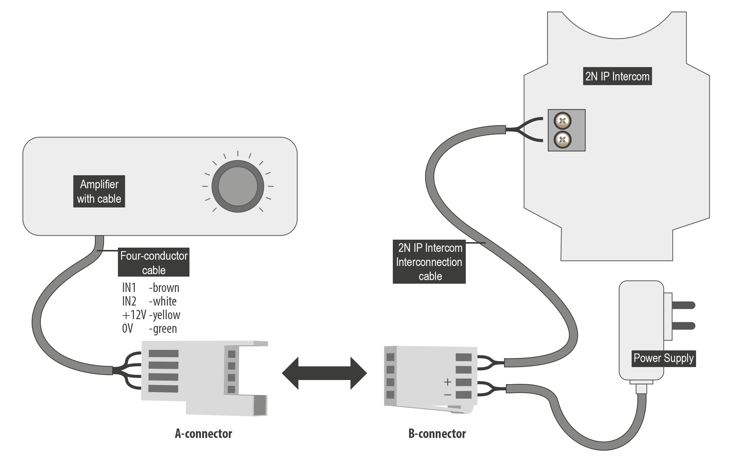
The induction loop amplifier can be wall mounted with the use of an internal induction loop where a signal covering is requested. Outdoor use is possible thanks to the IP65 covering. A four-wire cable of the length of one meter is mounted to the supplied product for easier connection to the intercom. In the cable are two wires for 12 V DC supply and two wires for signal input, the wires are connected into interconnection connector. If you shorten the cable, follow the colour marking.
Before wall mounting run the cable through the hole that you have prepared. Then mark two mounting holes on the wall, through the amplifier front. Remove the amplifier and drill the mounting holes. Use the plugs and screws included in the delivery. Use a drill of the diameter of 6 mm. After fastening, cover the screws with the blanks supplied.
Use the supplied connectors to connect the amplifier to the intercom and power supply. The A connector is connected to the amplifier four-wire cable. Insert a special intercom-connecting cable supplied with the amplifier and 12 V power supply outlets to the B connector. Connect the special cable to the intercom and connect the power supply to the mains. You can place the mated A and B connectors into the 2N IP intercom cover. The connectors help you connect stripped cables. Open the connector by pushing a thin screwdriver onto the white spots at its front and close the connector by sliding the movable part through a side gap.
Finally, test the amplifier function using a suitable receiver for hearing impaired persons or magnetic field communication tester. No other settings are required.
 |
Specifications:
- Supply voltage: 8–18 V DC
Supply current at 12 V supply:
1 Ω load, full power output; 1.4 A, sine wave signal; 1 A, pink noise signal
8 Ω load, half power output; 550 mA, sine wave signal; 400 mA, pink noise signal
no signal; 100 mA
standby; up to 10 mA
- Transition to standby w/o signal: 10 s
- Input level – basic: 100 mV – 6 Vrms
- Input level – increased: 1 V – 35 Vrms
- Input impedance: 2 kΩ parallel with 0.3 H
- Output current, 1 Ω load: 2.2 Arms (sine wave)
- Full power output: 1.6 Arms (pink noise)
- Output current, 8 Ω load: 730 mArms sine wave signal
- Half power output: 520 mArms pink noise signal
- Output short-circuit resistance: unlimited time
- Frequency characteristics: 100 Hz – 5KHz ±3 dB
- Temperature range: -20 – +50 °C
- Covering: IP65 (with round cable of 5–10 mm diameter)
- Dimensions: 144 x 100 x 31 mm
- Weight: 0.3 kg