2.2 Mechanical Installation
Overview of Installation Types
An overview of the installation types and the list of the required components are provided in the table below.
Installation type | Symbol | What you need for installation | |
|---|---|---|---|
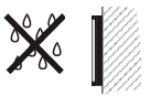
Indoor, on surface |
|
| |
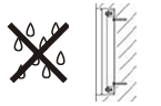
Indoor, flush mounting |
|
| |
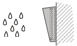
Outdoor, on surface |
|
| |
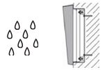
Outdoor, flush mounting |
|
| |
Indoor application means |
|
| |
Outdoor application means |
|
|


Caution
Before starting the mechanical installation on a selected place, make sure carefully that the preparations connected with it (drilling, wall cutting) cannot damage the electrical, gas, water and other existing wires and pipes.
- The warranty does not apply to the product defects and failures arisen as a result of improper mounting (in contradiction herewith). The manufacturer is neither liable for damage caused by theft within an area that is accessible after the attached electric lock is switched. The product is not designed as a burglar protection device except when used in combination with a standard lock, which has the security function.
- When the proper mounting instructions are not met, water might get in and destroy the electronics. It is because the intercom circuits are under continuous voltage and water infiltration causes an electro-chemical reaction. The manufacturer's warranty shall be void for products damaged in this way!
Surface Mounting
1. Drill holes according to the template included in the 2N® IP Vario supply. Insert the included dowels in the wall holes.
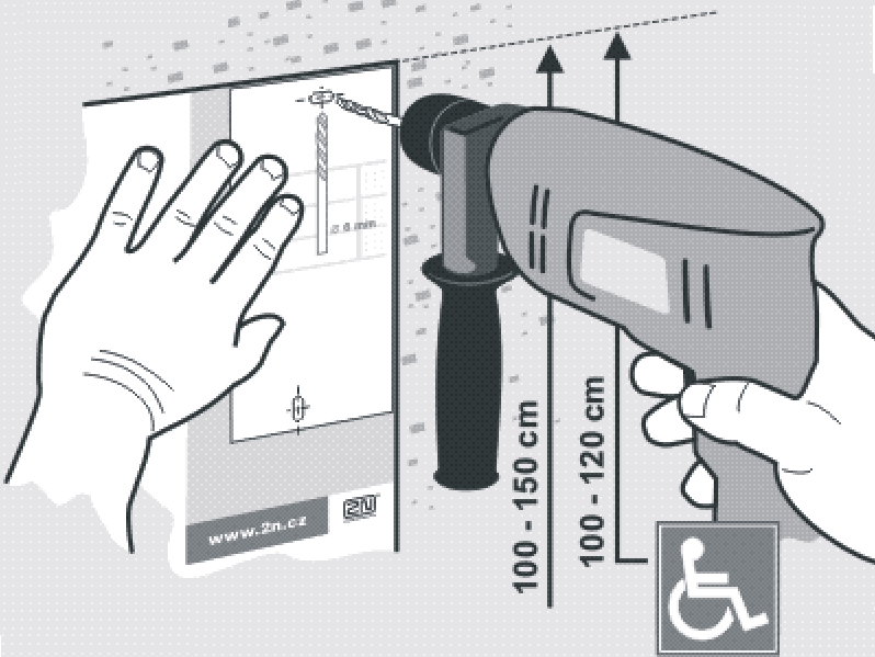 |
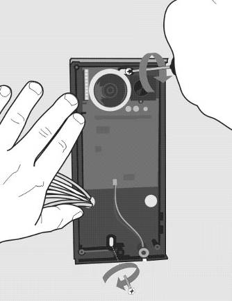
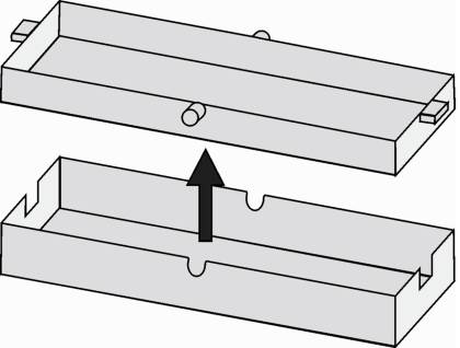
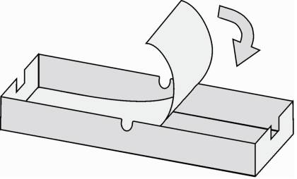
2. Use the hexagon key wrench included in the supply and remove the 2N® IP Vario metal cover. Remove the screw in the lower part of the metal cover and fold out the cover.
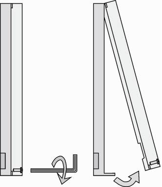 |
3. Use a cross-head screwdriver to remove the plastic cover and demount the cover.
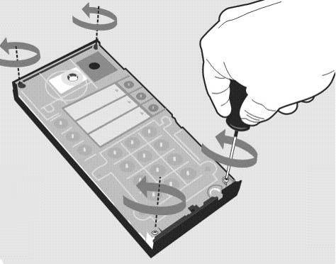 |
Warning
- Never remove the main board or camera electronics from under the lower cover while installing 2N® IP Vario. Do not disconnect the camera flat cable from the main board. Do not bend and press upon the flat cable either.
4. In multiple-module assemblies connect the boxes, placing the basic module to the left and the extending modules to the right. The interconnecting cable shall be connected later!
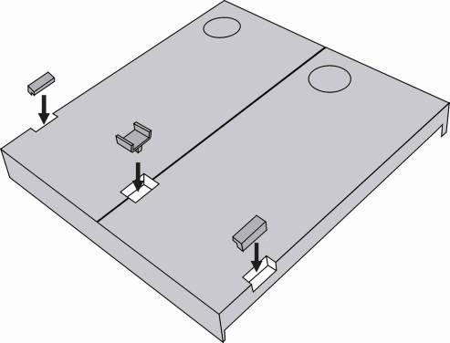 |
5. Install blank modules on the unused side holes as shown in Figure previous step.
6. If you are installing a roof module, put it on the wall now.
7. Fix 2N® IP Vario on the wall with screws. Carry the supply cables (Ethernet, lock, power cables) to the basic module box through one of the holes. Seal the screw hole carefully with some cement or non-aggressive silicone to avoid water infiltration.
 |
Warning
- Make sure that the mounting surface for the 2N® IP Vario door communicator is perfectly flat. Avoid mechanical overload upon the bottom part of the cover. An incorrect installation on an uneven surface may lead to cover deformation and thus product malfunctions.
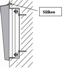
8. While installing a roof module, paste its top and side edges to the wall using silicone glue to prevent water from flowing into the box along or around the cables.
 |
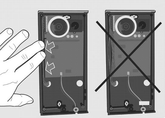
9. Connect the cables as described in subsection 2.4, Mounting – Electrical Installation. Make sure that the cables are not squeezed while installing the plastic cover. For the correct cable installation.
 |
10.Remove the protective foil from the display (for display-equipped 2N® IP Vario versions only).
11. Make sure that the cables are placed properly inside and that none of them obstructs a perfect cover closure.
12. Make sure that the three loudspeaker holder feet fit into the board holes. Keep the required loudspeaker position to make the seal work properly.
13.Having mounted the unit on the wall and connected all cables, replace the plastic cover using cross-recessed screws.
Warning
- Remember to tighten all the four corner screws to fix the loudspeaker seal after electric installation to avoid water in-leak! A PZ1 cross-head screwdriver is recommended.
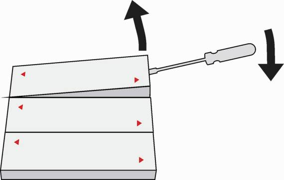
14. Take out the name plates from the plastic cover. Use a flat-bladed screwdriver, for example.
 |
15. Remove the inserts from the name plates.
 |
16. Insert the printed foil labels.
 |
17. Put the inserts back in the name plates.
18. Replace the name plates, clicking them into position. The name plates hold the matt foil inserted underneath.
19. Check whether a silicone seal is inserted in the top groove of the plastic cover. A spare seal package is included.
20. Close the metal cover and fix it with screws.
Outdoor Installation Rules
- Always connect button backlighting – it is used for heating.
- The joint between the roof module and the wall must be filled with a waterproof cement to prevent water in-leak (see Figure 2.5).
- Water must not leak in along or around the cables.
Warning
- Make sure that all the holes are filled with a waterproof material – top, around the cables and screws - and that a side sealing is ensured.
Name Tag Material and Printing
Each 2N® IP Vario package includes a sheet of transparent foil for laser printing. Cut the printed foil into pieces and insert the labels in the name plates. Do not use paper to avoid water in-leak and paper damage.
Red arrows are printed on the name plate. Make sure that the text and the arrow do not overlap. We recommend you to use a template (MS Word) available in section Downloads for printing.
Flush Mounting
Follow the installation instructions included in the flush mounting box delivery.
Caution
- The warranty shall not apply to product failures and defects caused by improper installation (contrary to these instructions). The manufacturer is neither liable for damages caused by theft within an area that is accessible after the attached electric lock is switched. The product is not designed as a burglar protection device except when used in combination with a standard lock, which has the security function.