2.5 Extending Module Connection
2N IP Vario allows to connect following extending modules:
- Extending button modules
- Additional Switch
- Internal RFID Card Reader 125 kHz
- Security Relay
- Wiegand Isolator
- Induction Loop
Caution
- In case the firmware versions of the module to be connected and the main unit are incompatible, the module will not be detected. Therefore, it is necessary to update the device firmware after the modules are connected. Use the device web interface in the System > Maintenance > System configuration section for firmware upgrade (see Configuration manual for 2N IP intercoms).
Extending button modules
2N IP Vario features an easy installation of extending button modules. Extending modules are connected using a single cable (included in every extender delivery) in a chain pattern (every additional unit is connected with the previous one). Each extending module has two connectors – an input connector (for connection towards the 2N IP Vario basic unit) and an output connector (for connection of another, more remote unit). Be sure to maintain the correct orientation of the units and avoid connector mismatch to ensure a proper function of the device!
|
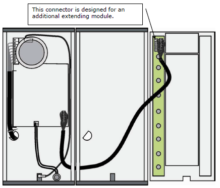
Connection of One-Row-Button Extending Modules
Maximum Count of Extenders
9135181E (1× 8 buttons) | 6 | 5 | 4 | 3 | 2 | 1 | 0 |
9135182E (2× 8 buttons) | 0 | 0 | 1 | 1 | 2 | 2 | 3 |
The table above shows how to combine modules with single (whole) and double buttons.
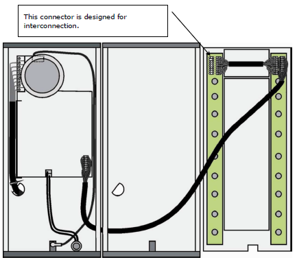
Module Cable Interconnection
- The cable is included in every extending module delivery. Both its ends are the same. Configuration is 1:1. Connectors cannot be shifted or inserted conversely because they are equipped with a so-called key.
- The basic unit is always on the left. Extenders are chain-connected, i.e. each is linked with its neighbour.
- The cable cannot be driven through the box interconnecting holes until the boxes have been connected (see subsection 2.3 Mounting – Mechanical Installation).
 |
Connection of Two-Button-Row Extending Module
Caution
- The extending modules must be connected mutually and with the basic unit by means of a formed piece supplied with the extending module!!!
Button Numbering
Button numbering – one-button with a whole-button set
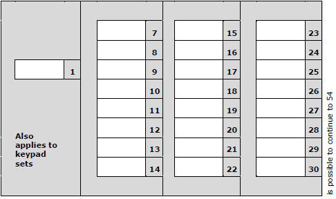 |
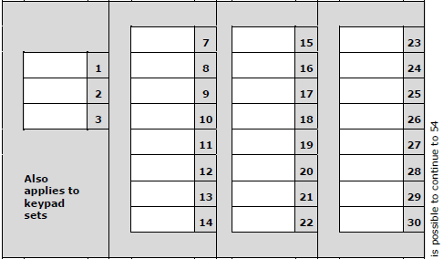
Button numbering – whole-button sets
|
Button numbering – double-button set
|
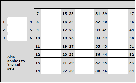
Button Numbering – Info Panel Sets
Installing the info panel name plate, Part No. 9135311E, into any of the extending modules will not change the numbering system (the buttons on the info panel sides will remain functional). Connecting the info panel module, Part No. 9135310E, will result in omission of eight numbers.
Additional Switch
The 2N Additional Switch (Part No. 9137310 E) is used to extend the 2N IP Vario door communicator with another switch. 2N Additional Switch is suitable for e.g. electric door lock or low voltage logical inputs of e.g. gate and barrier control systems.
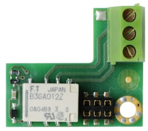 |
Function:
The 2N IP Vario Additional Switch adds one additional switch to the
2N IP Vario basic unit.
Specifications:
- Passive switch: NO and NC contacts, up to 30 V / 1 A AC/DC
Caution
- Before installing the module, make sure that the current and voltage limits of the module will not be exceeded in your application (refer to the Technical Parameters chapter). In no case use this module for mains voltage switching!
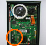
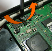
Module mounting:
Switch off the intercom before module installation.
 |
 |
 |
 |
 |
 |
Module settings:
Refer to the Configuration manual for 2N IP intercoms for details.
Connection:
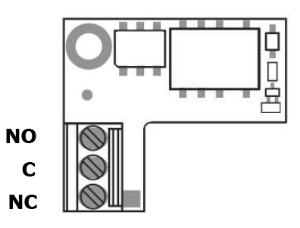 |
| Switch | Connection |
|---|---|
| Normally opened | NO – C |
| Normally closed | NC – C |
Internal RFID Card Reader 125 kHz
The Internal RFID Card Reader (Part No. 9137430 E) is used for reading RFID card Ids in the 125 kHz band. This module is intended for mounting into the 2N IP Vario model 91371....U.
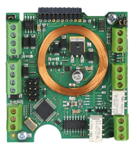 |
Function:
The 2N IP Vario Internal RFID Card Reader adds these features
- RFID card reader
- 2 relay outputs
- 2 digital inputs
- WIEGAND interface
- Signalling outputs (LED / buzzer)
Specifications:
Card reader
Compatible with EM4100 / EM4102 cards
Working frequency: 125 KHz
Minimum reading distance: 10 mm above 2N IP Vario cover
Relay outputs
Switching contact
30 V / 1 A AC / DC
Logical inputs
Active mode – requires external voltage (JP2 jumper OFF)
UIN-ON = min +2.5 V
UIN-OFF = max +1.5 V
UIN max = +48 V
IIN (UIN +48 V) = max 1 mA
Passive mode – requires external contact only (JP2 jumper ON)
UOUT = approx. 8.3 V
ILOOP = approx. 0.5 mA
Signalling outputs
5 V or 12V DC voltage
270 ohm current limiter
WIEGAND interface
Input / Output (as programmed)
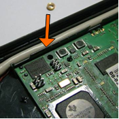
Module mounting:
- Power off 2N IP Vario.
- Use a hexagonal wrench to unscrew and remove the metal cover.
- Use a cross-head screwdriver to unscrew and remove the plastic cover.
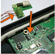
- Connect the reader module into the 2N IP Vario basic unit bottom connector making sure that the microphone cable lies under the module.
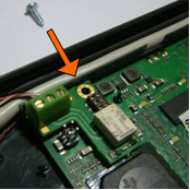
- Use the enclosed screws to fix the reader module to the 2N IP Vario plastic base.
- Connect the wires for the reader module interface(s) if necessary.
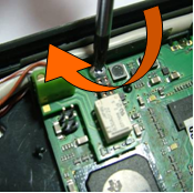
- Replace and fix the plastic cover using cross-head screws.
- Replace and screw back the metal cover.
Module settings:
Refer to the Configuration manual for 2N IP intercoms for details.
Connection:
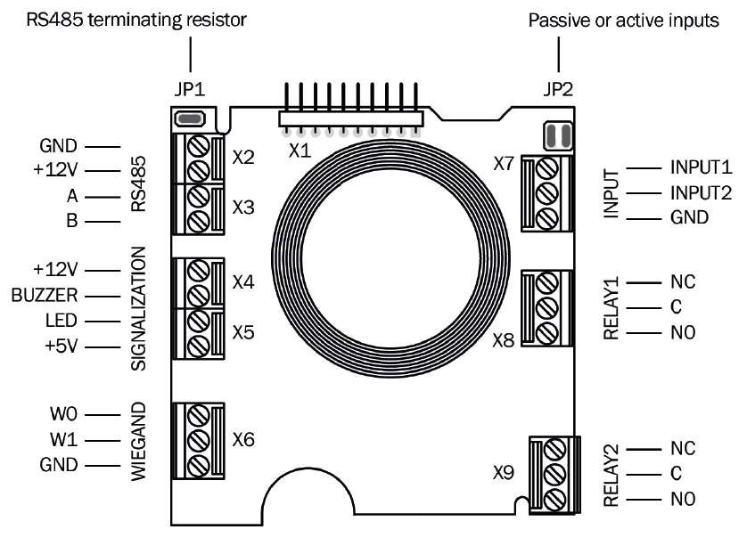 |
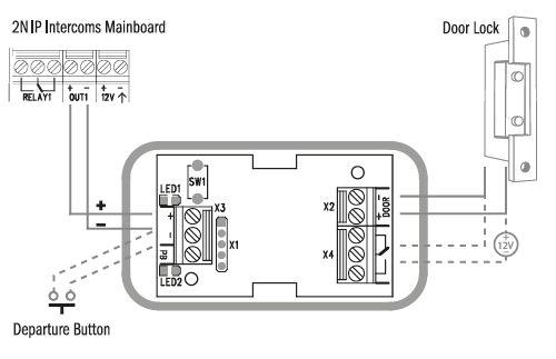
Security Relay
The 2N Security Relay (Part No. 9159010) is used for enhancing security between the intercom and the connected electric lock. The 2N Security Relay is designed for any 2N IP intercom model with firmware versions 1.15 and higher. It significantly enhances security of the connected electric lock as it prevents lock opening by forced intercom tampering.
 |
Function:
The 2N Security Relay is a device installed between an intercom (outside the secured area) and the electric lock (inside the secured area). The 2N Security Relay includes a relay that can only be activated if the valid opening code is received from the intercom.
Specifications:
Passive switch: NO and NC contacts, up to 30 V / 1 A AC/DC
Switched output:
- Where the security relay is fed from the intercom, 9 to 13 V DC is available on the output depending on the power supply (PoE: 9 V; adapter: source voltage of minus 1 V) / 400 mA DC.
- Where the security relay is fed from an external power supply, 12 V / 700 mA DC is available on the output.
Dimensions: (56 x 31 x 24) mm
Weight: 20 g
Installation:
Install the 2N Security Relay onto a two-wire cable between the intercom and the electric lock inside the area to be secured (typically behind the door). The device is powered and controlled via this two-wire cable and so can be added to an existing installation. Thanks to its compact dimensions, the device can be installed into a standard mounting box.
The Security relay is designed with holes for surface anchoring. It is recommended that a screw of the diameter of 3 mm with a lens head of the diameter of 6 mm is used. Using a countersunk head may cause irreversible damage to the plastic cover!
Connection:
Connect the 2N Security Relay to the intercom as follows:
- To the intercom active output (OUT1)
Connect the electric lock to the 2N Security Relay output as follows:
- To the switched output.
- To the passive output in series with the external power supply.
The device also supports a Departure button connected between the ‘PB’ and ‘- HeliosIP/IP Intercom’ terminals. Press the Departure button to activate the output for 5 seconds.
Status signalling:
| Green LED | Red LED | Status |
|---|---|---|
| blinking | off | Operational mode |
| on | off | Activated output |
| blinking | blinking | Programming mode – waiting for initialisation |
| on | blinking | Error – wrong code received |
Configuration:
- Connect the 2N Security Relay to the properly set intercom switch output; refer to the Configuration manual for 2N IP intercoms. Make sure that one LED at least on the 2N Security Relay is on or blinking.
- Press and hold the 2N Security Relay Reset button for 5 seconds to put the device in the programming mode (both the red and green LEDs are blinking).
- Activate the intercom switch using the keypad, telephone, etc. The first code sent from the intercom will be stored in the memory and considered valid. After code initialisation, the 2N IP Security Relay will pass into the operational mode (the green LED is blinking).
Caution
- In case of resetting the factory default settings on a device with a version of firmware 2.18 or higher it is necessary to reprogram the
2N Security Relay using the instructions above.
Connection:
 |
Tip
Video Tutorial: Security Relay Installation and Configuration
Wiegand Isolator
The 2N Wiegand Isolator (Part No. 9159011) is usef for galvanic isolation of the Wiegand bus.
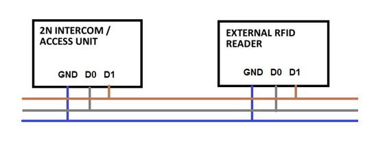
The 2N Wiegand Isolator is designed for galvanic isolation of two devices with separate power supply and interconnected via the Wiegand bus.
The 2N Wiegand Isolator protects the interconnected devices against communication errors and/or damage.
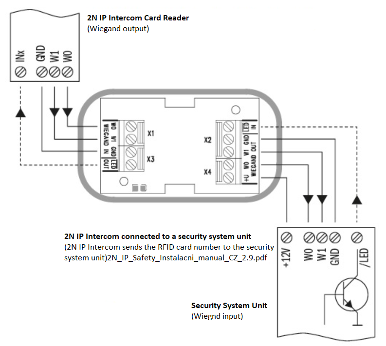
Connection of the 2N Card Reader to a security system unit is a typical example of application.
|
Function:
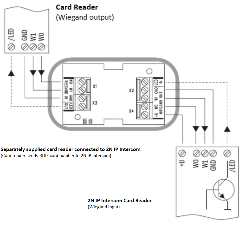
The 2N Wiegand Isolator separates galvanically a two-wire Wiegand bus in one direction and a status LED signal in the other direction. The module is power supplied from the Wiegand bus receiver side.
Specifications:
- 2-wire WIEGAND IN
- 2-wire WIEGAND OUT
- LED IN switched against GND on WIEGAND OUT side
- Open LED OUT switched against GND on WIEGAND IN side (up to 24 V / 50 mA)
- 5 to 16 V / 10 mA power supply from Wiegand bus receiver side
- 500 V DC isolation strength
Connection:
 |
 |
| Wiegand Input Technical Parameters | |
|---|---|
| Current | 5 mA |
| Input resistance | 680 Ohm |
| Pulse length | 50 μs |
| Delay between pulses | approx. 2 ms |
 |
Recommended Wiring Diagram for Reader with Bus Driver
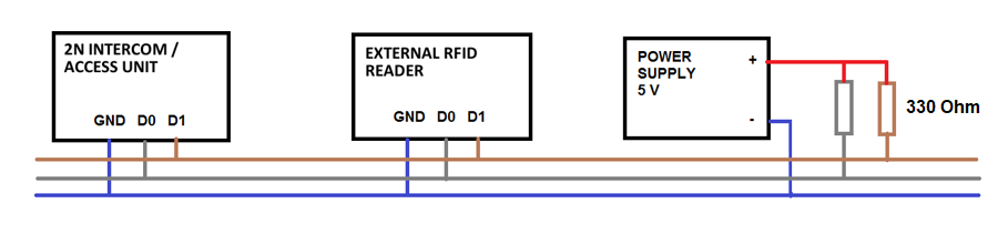 |
| Recommended Wiring Diagram for Reader with Open Collector (OC) Output |
Induction Loop
2N Induction Loop (Part No. 9159050 – Induction loop amplifier for 2N IP intercom, Part No. 9159054 – Induction loop amplifier without 2N IP intercom accessory, Part No. 9159052 - 12 V DC power adapter) is part of sound system installations for hearing impaired persons that are equipped with a special hearing aid capable of receiving reproduced sound via a magnetic field receiver. The system is defined by the IEC 60118-4 standard.
Installation:
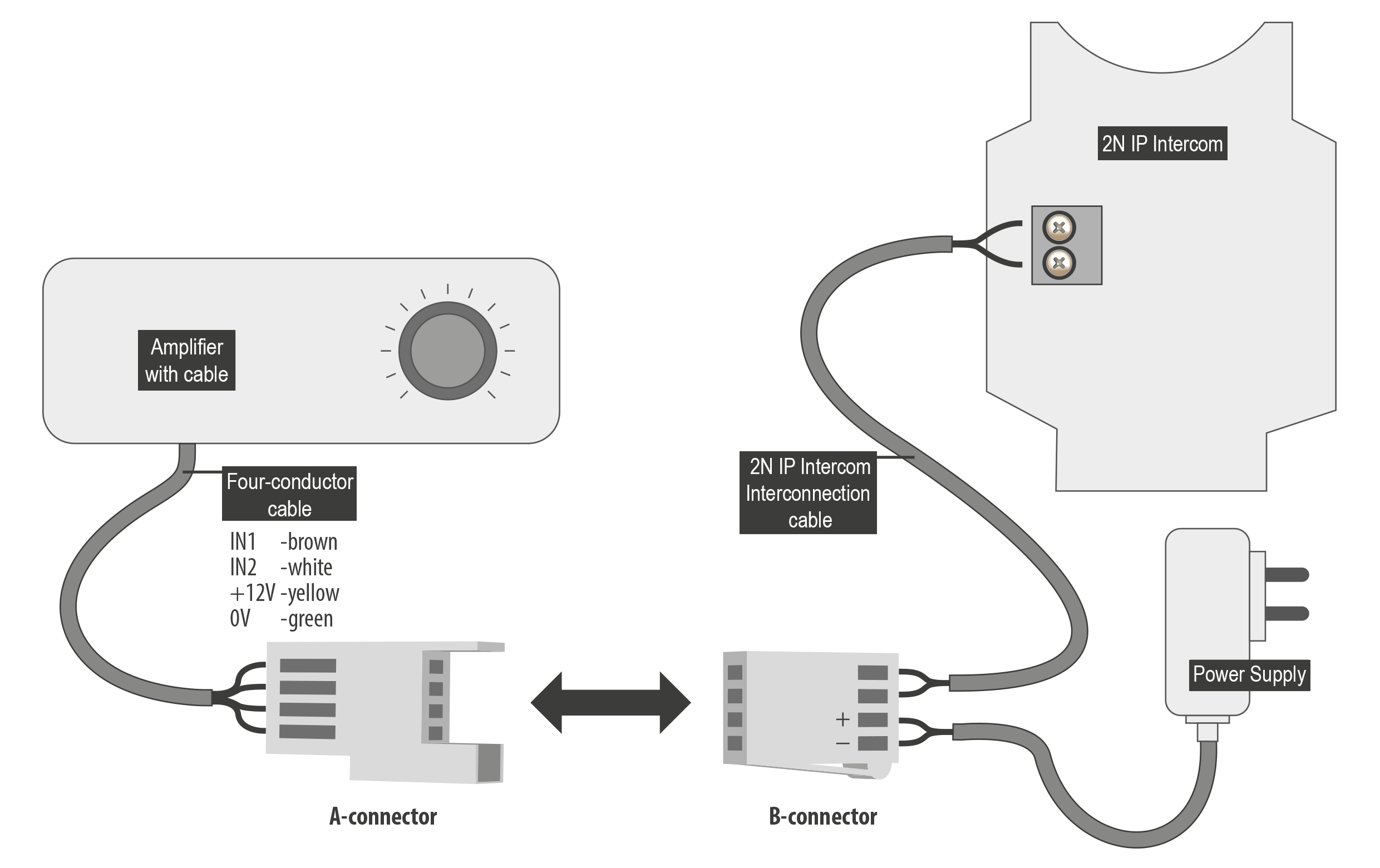
The induction loop amplifier can be wall mounted with the use of an internal induction loop where a signal covering is requested. Outdoor use is possible thanks to the IP65 covering. A four-wire cable of the length of one meter is mounted to the supplied product for easier connection to the intercom. In the cable are two wires for 12 V DC supply and two wires for signal input, the wires are connected into interconnection connector. If you shorten the cable, follow the colour marking.
Before wall mounting run the cable through the hole that you have prepared. Then mark two mounting holes on the wall, through the amplifier front. Remove the amplifier and drill the mounting holes. Use the plugs and screws included in the delivery. Use a drill of the diameter of 6 mm. After fastening, cover the screws with the blanks supplied.
Use the supplied connectors to connect the amplifier to the intercom and power supply. The A connector is connected to the amplifier four-wire cable. Insert a special intercom-connecting cable supplied with the amplifier and 12 V power supply outlets to the B connector. Connect the special cable to the intercom and connect the power supply to the mains. You can place the mated A and B connectors into the 2N IP intercom cover. The connectors help you connect stripped cables. Open the connector by pushing a thin screwdriver onto the white spots at its front and close the connector by sliding the movable part through a side gap.
Finally, test the amplifier function using a suitable receiver for hearing impaired persons or magnetic field communication tester. No other settings are required.
 |
Specifications:
- Supply voltage: 8–18 V DC
Supply current at 12 V supply:
1 Ω load, full power output; 1.4 A, sine wave signal; 1 A, pink noise signal
8 Ω load, half power output; 550 mA, sine wave signal; 400 mA, pink noise signal
standby, up to 10 mA
no signal, 100 mA
- Transition to standby w/o signal: 10 s
- Input level – basic: 100 mV – 6 Vrms
- Input level – increased: 1 V – 35 Vrms
- Input impedance: 2 kΩ parallel with 0.3 H
- Output current, 1 Ω load: 2.2 Arms (sine wave)
- Full power output: 1.6 Arms (pink noise)
- Output current, 8 Ω load: 730 mArms sine wave signal
- Half power output: 520 mArms pink noise signal
- Output short-circuit resistance: unlimited time
- Frequency characteristics: 100 Hz – 5 KHz ±3 dB
- Temperature range: -20 – +50 °C
- Covering: IP65 (with round cable of 5–10 mm diameter)
- Dimensions: 144 x 100 x 31 mm
- Weight: 0.3 kg