2.3 Electric Installation
This subsection describes how to install the modules, how to connect the 2N® IP Verso main unit to the power supply and LAN and how to connect other elements.
Caution
- The device must be part of the electrical system of the building.
Mounting Preparation
- Unscrew the second module cover on the main unit base.
- Use a flat screwdriver to take out the module cover.
Version A – 2-Module Base
- Place the base on the flush mounting box / predrilled holes with dowels and pull the cables through the bottom holes. Pull the Ethernet cable including the connector through the bottom hole to the left if necessary.
- Insert the metal fitting elements up and down and screw the base plate tight. You can level the base slightly if you are mounting just one base.
Version B – 3-Module Base
- Unscrew the cover of the additional base.
- Use a flat screwdriver to take out the cover.
- Slide the additional base to the main unit base and secure its position with the small side wedges and screws.
- Remove the microphone from the main unit base and loosen the microphone cable.
- Lead the microphone to the third module base as shown in the figure.
- Place the joined bases on the flush mounting box / predrilled holes with dowels and pull the cables through the bottom holes. Feed the Ethernet cable without the connector from the additional base to the main unit base if necessary.
Version C – Additional Columns
- Unscrew the cover of the additional bases and take it out with a flat screwdriver.
- Insert the bases into each other as projected and secure their position with the small side wedges and screws.
- Place the cover on the flush mounting box / predrilled holes with dowels and pull the cables if any through the bottom holes.
- Pull the bus using the cable bushing available in the flush mounting box.
Main Unit
Power Supply Connection
2N® IP Verso can be powered either from an external 12 V / 2 A DC source or directly from the LAN equipped with PoE 802.3af supporting network elements. Owing to different power outputs, the power supply selection affects the maximum count and applicability of the modules connected of the main unit.
Caution
- The external power supply should meet the PS2/LPS power supply class requirements.
External power supply
Use a 12 V ±15 % SELV supply dimensioned to the minimum current consumption of 2 A (Part No. 91341481E) to make your system work reliably. This power supply provides 2N® IP Verso with 24 W for feeding of the main unit and connected modules.
PoE Power Supply
2N® IP Verso is compatible with the PoE 802.3af (Class 0–12,95 W) technology and can be fed directly from the LAN via the compatible network elements. If your LAN does not support this technology, insert a PoE injector, Part No. 91378100, between 2N® IP Verso and the nearest network element. This power supply provides 2N® IP Verso with 12 W for feeding of the main unit and connected modules.
Combined Power Supply
2N® IP Verso can be fed from an external power supply and PoE at the same time. In this configuration, the maximum power for the connected modules is available.
LAN Connection
2N® IP Verso is connected to the Local Area Network (LAN) via the UTP/STP cable (Cat 5e or higher) terminated with an RJ-45 (LAN) connector. As the device is equipped with the Auto-MDIX function, both the straight and crossed cable can be used.
Caution
- We recommend the use of a LAN surge protection.
- We recommend the use of a shielded SSTP Ethernet cable with a shielded RJ-45 connector connected to the switch (with the grounding option) via the same shielded connector. This makes the device perfectly grounded.
Tip
- Remove the connector protecting cover to pass through the UTP/STP cable RJ terminal to the device box more easily.
Warning
-
This product cannot be connected directly to the telecommunications lines (or public wireless LANs) of any telecommunication carriers (e.g. mobile communications carriers, fixed communications carriers, or internet providers). In the case of connecting this product to the Internet, be sure to connect it via a router.
Main Unit Connector Configuration
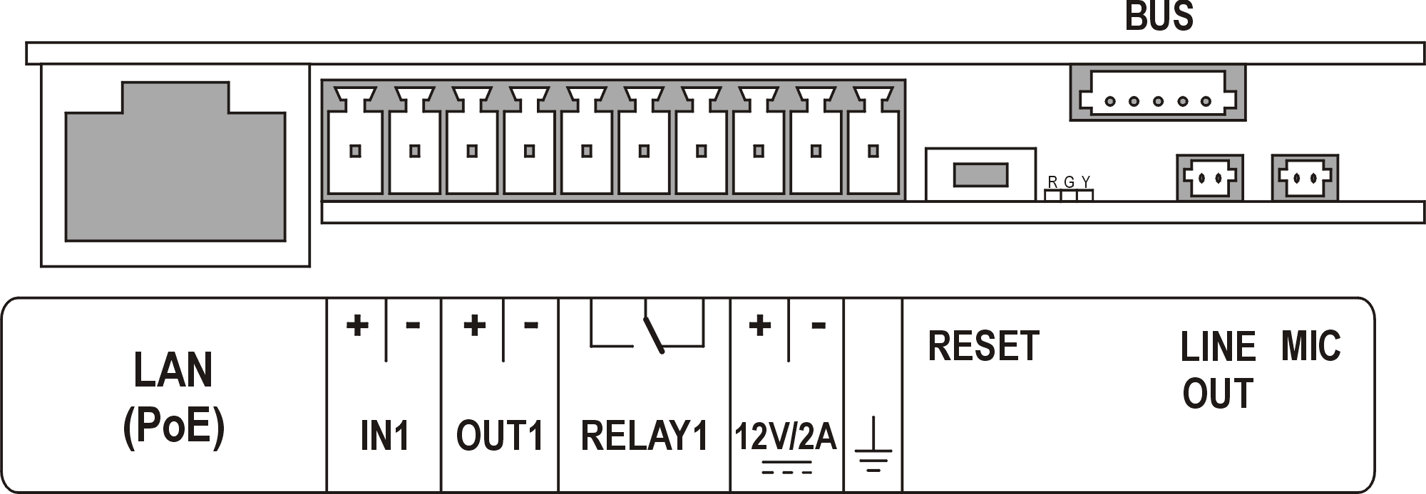 |
Caution
- We recommend you to use a grounding cable of the cross-section of 1.5 mm2.
| Legend | |
LAN (PoE) | LAN (PoE according to 802.3af) connector |
IN1 | IN1 terminals for input in passive/ active mode (−30 V to +30 V DC) OFF = open OR UIN > 1.5 V ON = closed contact OR UIN < 1.5 V |
OUT1 | OUT1 terminals of active input for 2N® Security Relay or electric lock connection 8 up to 12 V DC depending on power supply (PoE: 10 V; adaptor: power supply voltage minus 2 V), max 400 mA |
RELAY1 | RELAY1 terminals with accessible 30 V / 1 A AC/DC NO/NC contact. Used for connection of non-critical devices only (lights, e.g.). |
12V/2A | External 12 V / 2 A DC supply terminals |
GND | Grounding terminal |
RESET | RESET / FACTORY RESET button |
RGY | LED indicators (red/green/yellow) |
LINE OUT | LINE OUT connector (1 VRMS). Connector type JST SHR-02V-S. |
MIC | MIC connector for microphone connection |
BUS | 2N® IP Verso bus connector |
Tip
- Output wiring diagram for Relay terminals
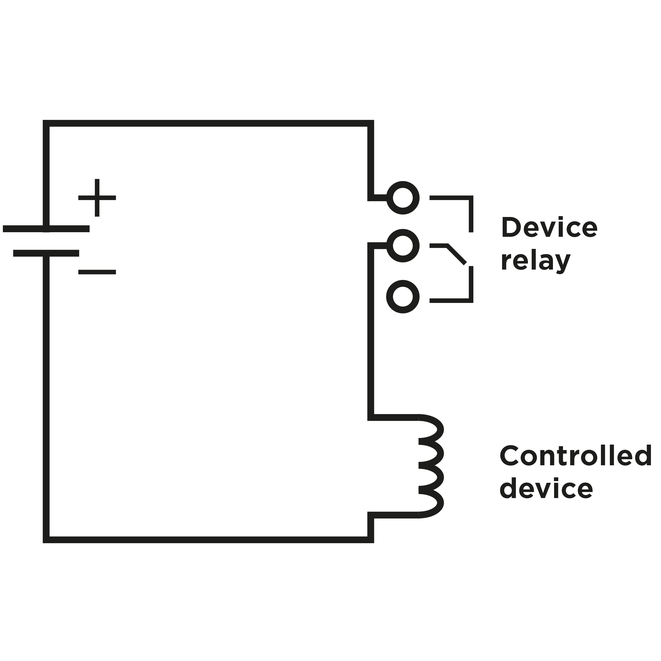 |
Wiring diagram for the controlled device’s electric circuit closing
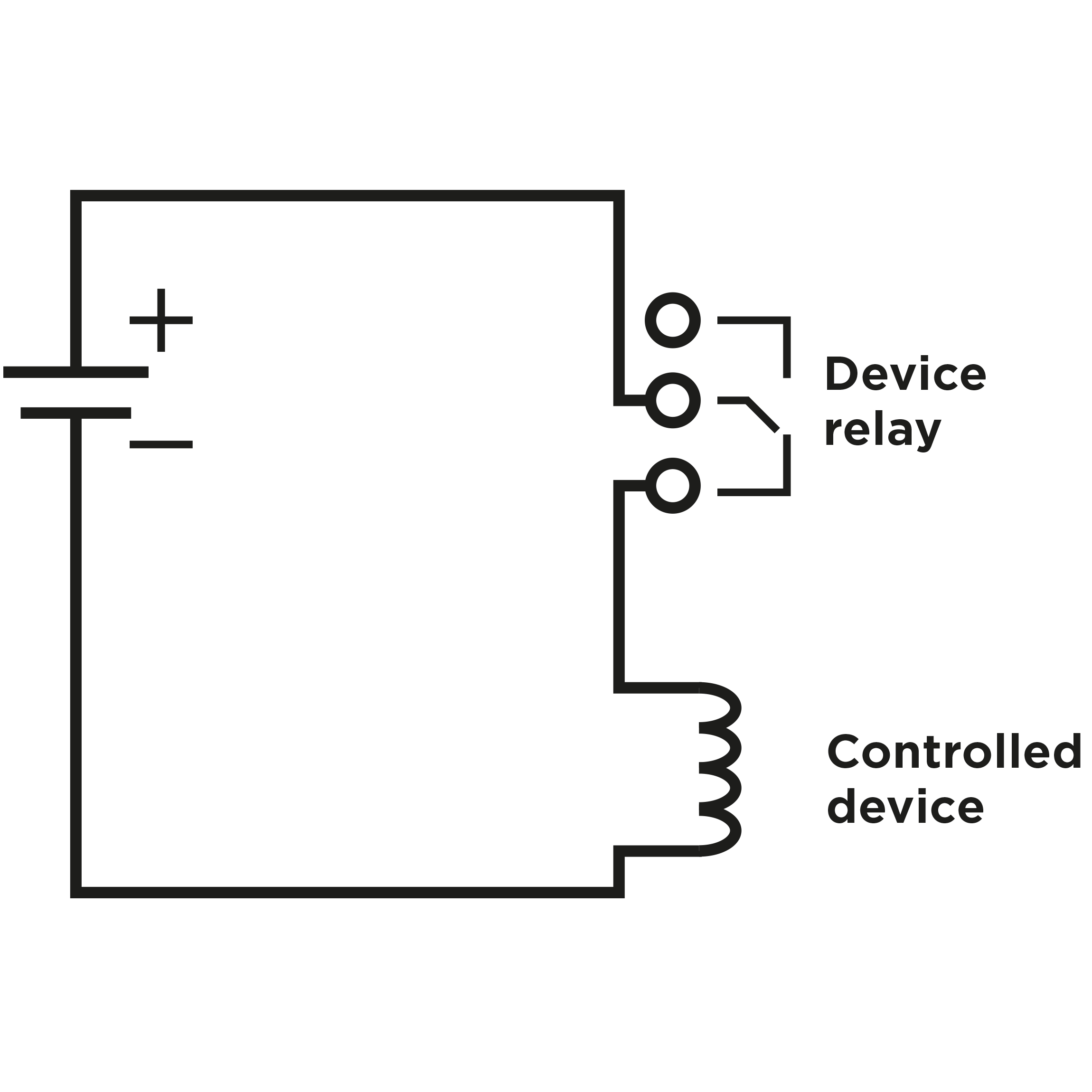 |
Wiring diagram for the controlled device’s electric circuit opening
Tip
- Wiring Diagram of IN1 connector in active mode
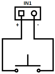 |
- Wiring Diagram of IN1 connector in passive mode
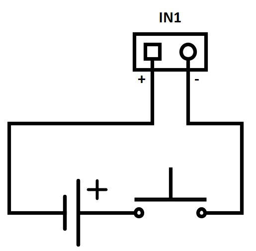 |
Reset Button
Located among the main unit connectors, the Reset button helps you reset the factory default values, restart the device, find the device IP address and switch the static/dynamic mode.
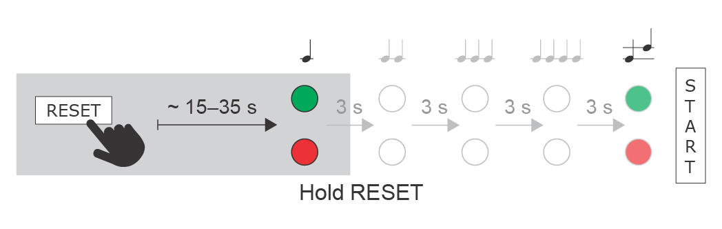
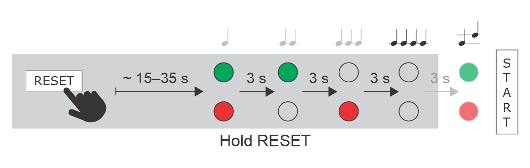
IP Address Finding
Follow the instructions below to retrieve the current IP address:
- Press and hold the RESET button.
- Wait until the red and green LEDs go on simultaneously on the device and the acoustic signal
 can be heard (approx. 15–35 s).
 - Release the RESET button.
- The device automatically announces the current IP address.
 |
Note
- The delay after pressing RESET till the first light and sound signalling is set to 15–35 s depending on the 2N IP intercom/answering unit model used.
- 18 s is the valid value for 2N® IP Verso.
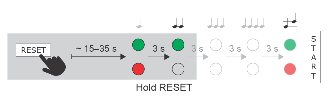
Static IP Address Setting
Follow the instructions below to switch on the Static IP address mode (DHCP OFF):
- Press and hold the RESET button.
- Wait until the red and green LEDs go on simultaneously on the device and the acoustic signal
 can be heard (approx. 15–35 s).
 - Wait until the red LED goes off and the acoustic signal
 can be heard (approx. for another 3 s).
 - Release the RESET button.
The following network parameters will be set after restart:
- IP address: 192.168.1.100
- Network mask: 255.255.255.0
- Default gateway: 192.168.1.1
 |
Dynamic IP Address Setting
Follow the instructions below to switch on the Dynamic IP address mode (DCHP ON):
- Press and hold the RESET button.
- Wait until the red and green LEDs go on simultaneously on the device and the acoustic signal can be heard (approx. 15–35 s).
- Wait until the red LED goes off and the acoustic signal can be heard (approx. for another 3 s).
- Wait until the green LED goes off and the red LED goes on again and the acoustic signal
 can be heard (approx. for another 3 s).
 - Release the RESET button.
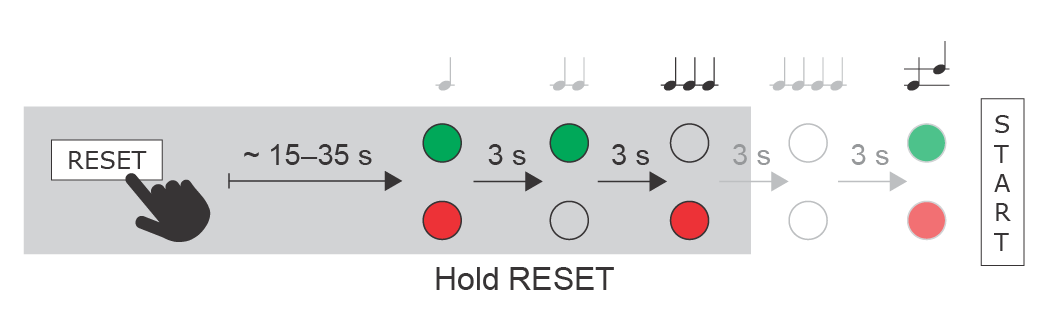 |
Factory Reset
Follow the instructions below to reset the factory default values:
- Press and hold the RESET button.
- Wait until the red and green LEDs go on simultaneously and the acoustic signal can be heard (approx. 15–35 s).
- Wait until the red LED goes off and the acoustic signal can be heard (approx. for another 3 s).
- Wait until the green LED goes off and the red LED goes on again and the acoustic signal can be heard (approx. for another 3 s).
- Wait until the red LED goes off and the acoustic signal
 can be heard (approx. for another 3 s).
 - Release the RESET button.
 |
Caution
- In case of resetting the factory default settings on a device with a version of firmware 2.18 or higher it is necessary to reprogram the
2N® Security Relay using the instructions from section 2.4.
Device Restart
Press the RESET button shortly (< 1 s) to restart the system without changing configuration.
Note
- The time interval between the short press of RESET and reconnection after restart is 26 s for 2N® IP Verso.
Available Switches
| Location | Name | Description |
|---|---|---|
| Main Unit | Relay 1 | Passive switch: NO/NC contact, up to 30 V / 1 A AC/DC. Used for connection of non-critical devices only (lights, e.g.). |
| Output 1 | Active switch output: 8 up to 12 V DC depending on power supply (PoE: 10 V; adaptor: power supply voltage minus 2 V), max 400 mA | |
I/O Module* (Part No. 9155034) | ext.relay1 | Passive relay switch: NO and NC contacts, up to 30 V / 1 A AC/DC. Used for connection of non-critical devices only (lights, e.g.). |
| ext.relay2 | Passive relay switch: NO and NC contacts, up to 30 V / 1 A AC/DC. Used for connection of non-critical devices only (lights, e.g.). |
More modules marked by * can be used.
Security
- The 12V output is used for lock connection. If, however, the unit (2N IP Intercom, 2N Access Unit) is installed where unauthorized tampering may happen, we strongly recommend that the 2N® Security Relay (Part No. 9159010) be used for enhanced installation security.
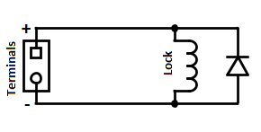
Warning
When you connect a device containing a coil, such as a relay or an electromagnetic lock, it is necessary to protect the intercom against voltage peak while switching off the induction load. For this way of protection we recommend a diode 1 A / 1000 V (e.g., 1N4007, 1N5407, 1N5408) connected antiparallel to the device.
 |
Main Unit LED Pictograms
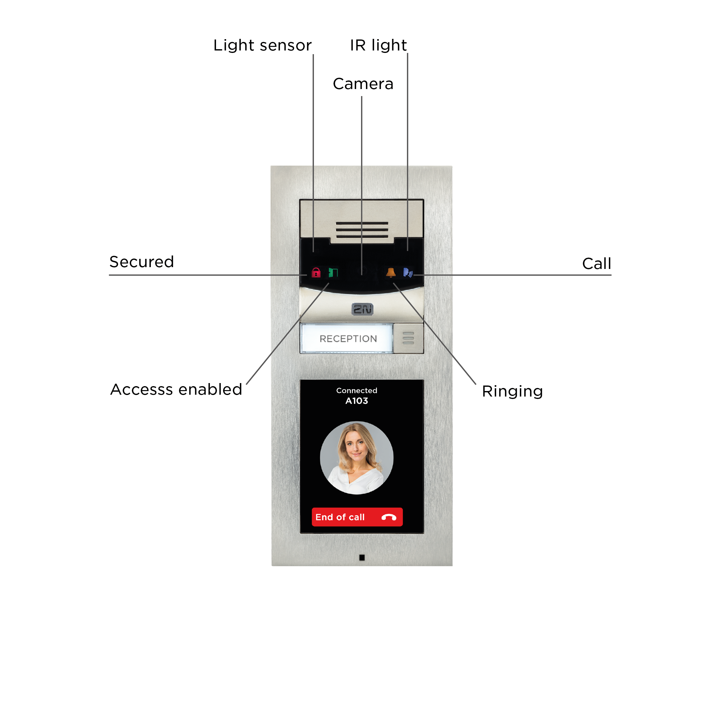 |
HW version 4 and higher
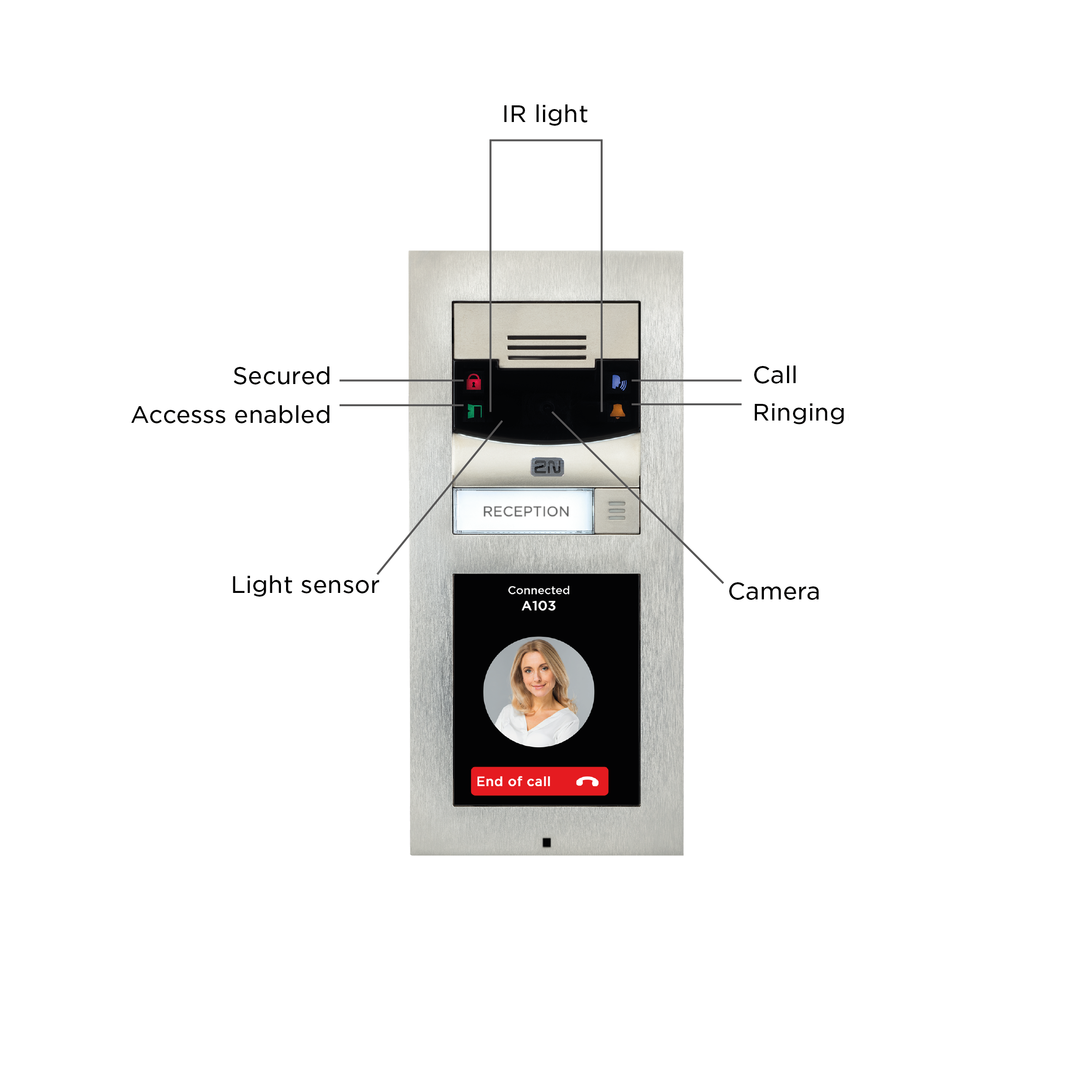 |
HW version 3 and lower