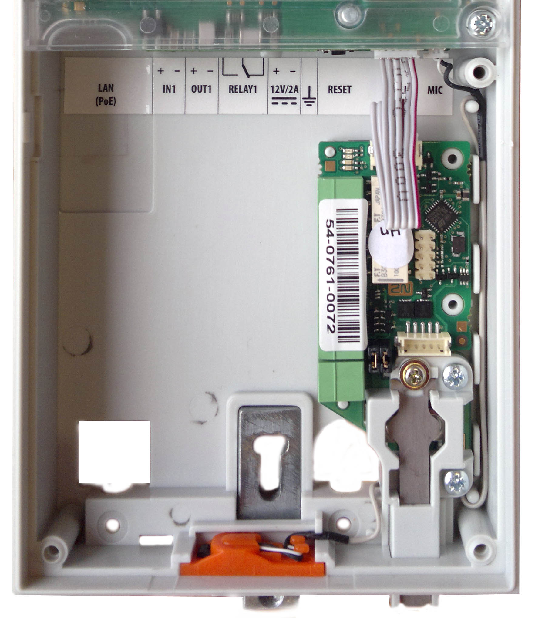
2.4 Extending Module Connection
2N® IP Verso allows you to connect the following extending modules:
- Infopanel
- Keypad
- Touch Keypad
- RFID Card Reader 125 kHz
- RFID Card Reader 13.56 MHz, NFC Support
- Secured RFID Card Reader 13.56 MHz, NFC Support
- Bluetooth & RFID Reader 125kHz, 13.56 MHz, NFC
- Bluetooth & RFID Reader 125kHz, secured 13.56 MHz, NFC
- Touch Keypad & RFID Reader 125 kHz, 13.56MHz, NFC
- Touch Keypad & RFID Reader 125 kHz, secured 13.56 MHz, NFC
- Touch Keypad & Bluetooth & RFID Reader 125 kHz, 13.56MHz, NFC
- Touch Keypad & Bluetooth & RFID Reader 125 kHz, secured 13.56 MHz, NFC
- Bluetooth Reader
- Touch Display
- Induction Loop
- Fingerprint Reader
- I/O Module
- 5-Button
- OSDP Module
- Wiegand Module
- Tamper Switch
- Blind Panel
- Security Relay
Module Bus Interconnection
Caution
- In case the firmware versions of the module to be connected and the main unit are incompatible, the module will not be detected. Therefore, it is necessary to update the device firmware after the modules are connected. Use the device web interface in the System > Maintenance > System configuration section for firmware upgrade (see Configuration manual for 2N IP intercoms).
All the 2N® IP Verso modules, except for the Tamper switch, are interconnected via a bus. The bus starts on the main unit and goes over all the modules. The order of modules on the bus is irrelevant. And it also irrelevant which bus connector on the module is used as the input and which is used as the output.
The modules include a 220 mm long interconnecting cable; the Wiegand (9155037), I/O modules (9155034) and OSDP modules (91550371) include an 80 mm long interconnecting cable.
It is possible to order separate bus cables of the lengths of 1 m, 3 m, or 5 m (Part Nos. 9155050/9155054/9155055), which are designed for remote 2N® IP Verso module installations. Typically, they are used for an RFID card reader mounted on a wall opposite to the 2N® IP Verso installation. The cable may be used only once on the bus. In extensive installations, the total bus cable length may not exceed 7 m.
The modules can be combined in each base as follows:
| Module | External mounting into main unit base (visible module) | Internal mounting into main unit base (invisible module) | Internal mounting onto main unit base bottom edge |
|---|---|---|---|
| Infopanel | X | ||
| Keypad | X | ||
| Touch keypad | X | ||
RFID card reader 125 kHz | X | ||
RFID card reader 13.56 MHz | X | ||
| RFID card reader 13.56 MHz NFC support | X | ||
| Secured RFID card reader 13.56 MHz NFC | X | ||
| Bluetooth & RFID reader 125 kHz, 13.56 MHz, NFC | X | ||
| Bluetooth & RFID reader 125 kHz, secured 13.56 MHz, NFC | X | ||
| Touch keypad & RFID reader 125 kHz, 13.56 MHz, NFC | X | ||
| Touch keypad & RFID reader 125 kHz, secured 13.56 MHz, NFC | X | ||
| Bluetooth reader | X |
| |
| Touch display | X | ||
| Induction loop | X | ||
| Fingerprint reader | X | ||
| I/O module | X | ||
| 5-button | X | ||
| OSDP | X | ||
| Wiegand | X | ||
| Tamper switch | X | ||
| Blind | X | ||
| Security Relay | X |
Module Power Supply
With the exception of the Tamper switch module, all the 2N® IP Verso modules are powered from the bus. The available bus power output depends on the power supply type. Main units 571v3 and higher can use a 3A power supply to increase the bus power available for the modules connected.
| Power supply | Specification | Available power |
|---|---|---|
| External supply | 12 V ±15% / 2 A (3 A) | 24 W (36 W) |
| PoE | 802.3af (Class 0–12.95 W) | 12 W |
| Combined | External supply + PoE | 30 W (42 W) |
The count of modules on the bus is limited by the available power supply output. The maximum count of the modules on the bus is 30.
Main unit (571v3) | Consumption [W] (Maximum value) |
|---|---|
| At relax | 2.376 |
| Infrared illumination | 3.06 |
| LED – call | 0.072 |
| LED – ringing | 0.072 |
| LED – lock | 0.072 |
| LED – secured | 0.096 |
| Button backlight | 0.072 |
| Name tag backlight | 0.072 |
| Unit backlight | 0.072 |
| Relay 1 | 0.132 |
| OUT 1 | 4.8 |
| Audio | 2.94 |
| Total | 13.84 |
| Module | Idle consumption [W] (Minimum value) | Full load [W] (Maximum value) | Special elements [W] |
|---|---|---|---|
| Main unit with camera | 2.36 | 11.57 | |
| Main unit without camera | 2.12 | 11.57 | |
| Infopanel | 0.17 | 0.35 | |
| Keypad | 0.19 | 1.16 | |
| RFID card reader 125 kHz | 0.52 | 1.31 | |
| RFID card reader 13.56 MHz | 0.44 | 0.82 | |
| RFID card reader 13.56 MHz NFC | 0.44 | 0.82 | |
| Secured RFID card reader 13.56 MHz NFC | 0.44 | 0.82 | |
| Bluetooth & RFID reader 125 kHz, 13.56 MHz, NFC | 1.34 | 2.74 | |
| Bluetooth & RFID reader 125 kHz, secured 13.56 MHz, NFC | 1.34 | 2.74 | |
| Touch keypad & RFID reader 125 kHz, 13.56 MHz, NFC | 1.38 | 2.52 | |
| Touch keypad & RFID reader 125 kHz, secured 13.56 MHz, NFC | 1.38 | 2.52 | |
| Bluetooth reader | 0.20 | 0.67 | |
| Touch display | 0.19 | 1.70 | |
| Induction loop | 0.18 | 0.84 | |
| Fingerprint reader | 0.73 | 1.54 | |
| I/O | 0.31 | 0.65 | Closed relay 0.13 |
| 5-button | 0.19 | 1.16 | |
| OSDP | 0.52 | 0.52 | |
| Wiegand | 0.46 | 0.46 | |
| Tamper switch | 0.31 | 0.65 | |
| Blind panel | x | x |
Specimen configuration consumption computation
| Module | Minimum consumption [W] | Maximum consumption [W] |
|---|---|---|
| Main unit with camera | 2.36 | 11.57 |
| RFID card reader 13.56 MHz | 0.44 | 0.82 |
| I/O | 0.31 | 0.65 |
| 5-button | 0.19 | 1.16 |
| Touch display | 1.16 | 2.02 |
| I/O | 0.31 | 0.65 |
| Tamper switch | 0.31 | 0.65 |
| Wiegand | 0.46 | 0.46 |
| Bluetooth reader | 0.20 | 0.67 |
| Total | 5.74 | 18.65 |
It is obvious from the specimen configuration that all the modules have sufficient outputs when an external power supply is used. When a PoE supply is used, the power output is insufficient for all the modules, which results in automatic decrease in backlight level, active output current supply, volume and LED intensity. Some modules need a specific power output for their specific activities: the I/O module, e.g., requires 0.13 W for relay closing (not calculated for minimum consumption).
Infopanel
The Infopanel (Part No. 9155030) is one of the 2N® IP Verso intercom elements and is used for inserting and backlighting printed information.
- The module contains two 2N® IP Verso bus connectors.
- These two connectors are fully interchangeable and can be used both as inputs from the main unit and outputs to other modules.
- If this module is the last one on the bus, one of the connectors remains unconnected.
- The module package includes a 220 mm long interconnecting cable.
- Nametag dimensions: 69.2 (W) x 86.7 (H) mm (dimensional tolerance: +0; −0.5 mm).
- Refer to www.2n.com for the printing template.
Keypad
The Keypad (Part No. 9155031) is one of the 2N® IP Verso intercom elements and provides a numerical input in the system.
- The module contains two 2N® IP Verso bus connectors.
- These two connectors are fully interchangeable and can be used both as inputs from the main unit and outputs to other modules.
- If this module is the last one on the bus, one of the connectors remains unconnected.
- The module package includes a 220 mm long interconnecting cable.
Touch Keypad
The Touch keypad (Part No. 9155047) is one of the 2N® IP Verso intercom elements and provides a numerical input in the system.
- The module contains two 2N® IP Verso bus connectors.
- These two connectors are fully interchangeable and can be used both as inputs from the main unit and outputs to other modules.
- If this module is the last one on the bus, one of the connectors remains unconnected.
- The module package includes a 220 mm long interconnecting cable.
RFID Card Reader Module 125 kHz
The 125 kHz RFID card reader (Part No. 9155032) is one of the 2N® IP Verso intercom elements and is used for reading RFID card Ids in the 125 kHz band.
- The module contains two 2N® IP Verso bus connectors.
- These two connectors are fully interchangeable and can be used both as inputs from the main unit and outputs to other modules.
- If this module is the last one on the bus, one of the connectors remains unconnected.
- The module package includes a 220 mm long interconnecting cable.
The following RFID cards can be read:
- EM4xxx
Caution
- To increase the reader's reading distance in combination with a touch display in a single installation, we recommend you to pull the M-Bus and LAN cables through separate bushings to avoid their crossing.
RFID Card Reader 13.56 MHz, NFC Support
The 13.56 MHz NFC RFID card reader (Part No. 9155040) is one of the 2N® IP Verso intercom elements and is used for reading RFID card Ids in the 13.56 MHz band.
- The module contains two 2N® IP Verso bus connectors.
- These two connectors are fully interchangeable and can be used both as inputs from the main unit and outputs to other modules.
- If this module is the last one on the bus, one of the connectors remains unconnected.
- The module package includes a 220 mm long interconnecting cable.
The following RFID cards can be read (only the card serial number is read):
- ISO14443A (Mifare, DESFire)
- PicoPass (HID iClass)
- FeliCa
- ST SR(IX)
- 2N® Mobile Key
Secured RFID Card Reader 13.56 MHz, NFC Support
The Secured 13.56 MHz NFC RFID card reader (Part No. 9155086) is one of the 2N® IP Verso intercom elements and is used for reading RFID card Ids in the 13.56 MHz band.
- The module contains two 2N® IP Verso bus connectors.
- These two connectors are fully interchangeable and can be used both as inputs from the main unit and outputs to other modules.
- If this module is the last one on the bus, one of the connectors remains unconnected.
- The module package includes a 220 mm long interconnecting cable.
The following RFID cards can be read (optionally the card serial number or PAC ID is read):
- ISO14443A (Mifare, DESFire)
- PicoPass (HID iClass)
- FeliCa
- ST SR(IX)
- 2N® Mobile Key
HID SE (Seos, iClass SE, Mifare SE)
Bluetooth & RFID Reader 125 kHz, 13.56 MHz, NFC
Bluetooth with a combined 125 kHz and 13.56 MHz NFC card reader module (Part No. 9155082, 91550945) is one of the 2N® IP Verso intercom elements and is used for Smartphone/2N® Mobile Key tablet/card access control, making user calls and/or other functions.
- NFC – a licensed function, for 2N® Mobile Key for Android only.
- The module contains two 2N® IP Verso bus connectors.
- These two connectors are fully interchangeable and can be used either as inputs from the main unit or outputs to other modules.
- If this module is the last one on the bus, one of the connectors remains unconnected.
- The module package includes a 220 mm long interconnecting cable.
The following RFID cards can be read:
125 kHz
- EM4xxx
13.56 MHz
- ISO14443A (Mifare, DESFire)
- PicoPass (HID iClass)
- FeliCa
- ST SR(IX)
2N® Mobile Key
Tip
- To accelerate card reading, it is recommended that you select the card types used by the user in the module settings.
Caution
- 2N® IP Verso supports one Bluetooth module connection only. If connected at the same time, multiple Bluetooth modules may result in an undesired behaviour.
Bluetooth & RFID Reader 125 kHz, Secured 13.56 MHz, NFC
Bluetooth with a combined 125 kHz and secured 13.56 MHz NFC card reader (Part No. 9155084) is one of the 2N® IP Verso intercom elements and is used for Smartphone/2N® Mobile Key tablet/card access control, making user calls and/or other functions.
- NFC – a licensed function, for 2N® Mobile Key for Android only.
- The module contains two 2N® IP Verso bus connectors.
- These two connectors are fully interchangeable and can be used either as inputs from the main unit or outputs to other modules.
- If this module is the last one on the bus, one of the connectors remains unconnected.
- The module package includes a 220 mm long interconnecting cable.
The following RFID cards can be read:
125 kHz
EM4xxx
- 13.56 MHz
- ISO14443A (Mifare, DESFire)
- PicoPass (HID iClass)
- FeliCa
- ST SR(IX)
- 2N® Mobile Key
- HID SE (Seos, iClass SE, Mifare SE)
Tip
- To accelerate card reading, it is recommended that you select the card types used by the user in the module settings.
Caution
- 2N® IP Verso supports one Bluetooth module connection only. If connected at the same time, multiple Bluetooth modules may result in an undesired behaviour.
Touch Keypad & RFID Reader 125 kHz, 13.56 MHz, NFC
The Touch keypad with a combined 125 kHz and 13.56 MHz NFC card reader (Part No. 9155081, 9155946) is one of the 2N® IP Verso intercom elements and is used for code/card access control, making user calls and/or other functions. The keypad surface is very sensitive yet weatherproof at the same time.
- NFC – a licensed function, for 2N® Mobile Key for Android only.
- The module contains two 2N® IP Verso bus connectors.
- These two connectors are fully interchangeable and can be used either as inputs from the main unit or outputs to other modules.
- If this module is the last one on the bus, one of the connectors remains unconnected.
- The module package includes a 220 mm long interconnecting cable.
The following RFID cards can be read:
125 kHz
- EM4xxx
13.56 MHz
- ISO14443A (Mifare, DESFire)
- PicoPass (HID iClass)
- FeliCa
- ST SR(IX)
2N® Mobile Key
Tip
- To accelerate card reading, it is recommended that you select the card types used by the user in the module settings.
Touch Keypad & RFID Reader 125 kHz, Secured 13.56 MHz, NFC
The Touch keypad with a combined 125 kHz and secured 13.56 MHz NFC card reader (Part No. 9155083) is one of the 2N® IP Verso intercom elements and is used for code/card access control, making user calls and/or other functions. The keypad surface is very sensitive yet weatherproof at the same time.
- NFC – a licensed function, for 2N® Mobile Key for Android only.
- The module contains two 2N® IP Verso bus connectors.
- These two connectors are fully interchangeable and can be used either as inputs from the main unit or outputs to other modules.
- If this module is the last one on the bus, one of the connectors remains unconnected.
- The module package includes a 220 mm long interconnecting cable.
The following RFID cards can be read:
125 kHz
EM4xxx
- 13.56 MHz
- ISO14443A (Mifare, DESFire)
- PicoPass (HID iClass)
- FeliCa
- ST SR(IX)
- 2N® Mobile Key
- HID SE (Seos, iClass SE, Mifare SE)
Tip
- To accelerate card reading, it is recommended that you select the card types used by the user in the module settings.
Touch Keypad & Bluetooth & RFID Reader 125 kHz, 13.56 MHz, NFC
The touch keypad with Bluetooth and a combined 125 kHz and secured 13.56 MHz card reader (Part No. 91550947) is one of the 2N® IP Verso intercom elements and is used for code/card access control using a smartphone or tablet with the 2N® Mobile Key application, making user calls and/or control of other functions. The keypad surface is very sensitive yet weatherproof at the same time.
- NFC – a licensed function, for 2N® Mobile Key for Android only.
- The module contains two bus connectors.
- These two connectors are fully interchangeable and can be used either as inputs from the main unit or outputs to other modules.
- If this module is the last one on the bus, one of the connectors remains unconnected.
- The module package includes a 220 mm long interconnecting cable.
The following RFID cards can be read:
125 kHz
EM4xxx
- 13.56 MHz
- ISO14443A (Mifare, DESFire)
- PicoPass (HID iClass)
- FeliCa
- ST SR(IX)
- 2N® Mobile Key
Touch Keypad & Bluetooth & RFID Reader 125kHz, Secured 13.56 MHz, NFC
The touch keypad with Bluetooth and a combined 125 kHz and secured 13.56 MHz card reader (Part No. 91550947-S) is one of the 2N® IP Verso intercom elements and is used for code/card access control using a smartphone or tablet with the 2N® Mobile Key application, making user calls and/or control of other functions. The keypad surface is very sensitive yet weatherproof at the same time.
- NFC – a licensed function, for 2N® Mobile Key for Android only.
- The module contains two bus connectors.
- These two connectors are fully interchangeable and can be used either as inputs from the main unit or outputs to other modules.
- If this module is the last one on the bus, one of the connectors remains unconnected.
- The module package includes a 220 mm long interconnecting cable.
The following RFID cards can be read:
125 kHz
EM4xxx
- 13.56 MHz
- ISO14443A (Mifare, DESFire)
- PicoPass (HID iClass)
- FeliCa
- ST SR(IX)
- 2N® Mobile Key
- HID SE (Seos, iClass SE, Mifare SE)
Caution
Press the button with a key symbol on the reader (without entering numbers before) of the touch keypad & Bluetooth & RFID reader module to start Bluetooth authentication.
Tip
- To accelerate card reading, it is recommended that you select the card types used by the user in the module settings.
Bluetooth Reader
- The Bluetooth reader (Part No. 9155046) is one of the 2N® IP Verso intercom elements and helps authenticate and subsequently open doors using Android and iOS based smartphones via the Bluetooth protocol 4.0 as RFID card replacement. Install the 2N® Mobile Key application from Google Play and Appstore to make authentication work properly. The application requires phones with Android OS 6 and higher and iOS 12 and higher.
- The module contains two 2N® IP Verso bus connectors.
- The two connectors are fully interchangeable and can be used both as inputs from the main unit or outputs to other modules.
- If this module is the last one on the bus, one of the connectors remains unconnected.
- The package includes a 220 mm long interconnecting cable.
- The module uses the 2.4 GHz frequency.
IDs from the following smart phones can be read:
- Android 6 and higher
- iOS 12 and higher
Caution
- 2N® IP Verso supports one Bluetooth module connection only. If connected at the same time, multiple Bluetooth modules may result in an undesired behaviour.
Touch Display
The Touch display (Part No. 9155036) is designed for the 2N® IP Verso communicator. This module can be used as:
- Infopanel module – displays user defined image sequences
- Keypad module – virtual touch keypad
- Button module – virtual phone directory
Module connection options:
- The module contains two 2N® IP Verso bus connectors.
- These two connectors are fully interchangeable and can be used both as inputs from the main unit and outputs to other modules.
- If this module is the last one on the bus, one of the connectors remains unconnected.
- The module package includes a 220 mm long interconnecting cable.
Technical specification:
- Resolution: 320 px x 214 px H x V
- Resolution slideshow: 214 px x 214 px
- Contrast ratio: 400
- Brightness: 350 cd/m2
- Weight: 280 g
- Working temperature: −20 °C – 60 °C
- Resistance level: IK07
Induction Loop
The Induction loop (Part No. 9155041) is one of the 2N® IP Verso intercom elements and is used to transmit an audio signal directly into a hearing aid via a magnetic field.
- The module contains two 2N® IP Verso bus connectors.
- These two connectors are fully interchangeable and can be used both as inputs from the main unit and outputs to other modules.
- If this module is the last one on the bus, one of the connectors remains unconnected.
- The module package includes a 220 mm long interconnecting cable.
- Used mode: Telecoil (also referred to as t-switch or t-coil)
- Maximum power: 2W
- Frequency range: 100 Hz – 5 kHz / ± 3 dB
- External antenna can be connected – Part No. 9155043
- Short circuit resistance: without limitation
Fingerprint Reader
The Fingerprint reader (Part No. 9155045) is one of the 2N® IP Verso intercom modules and is used for automated verification of human fingers for access control and intercom control.
- The module contains two 2N® IP Verso bus connectors.
- These two connectors are fully interchangeable and can be used both as inputs from the main unit and outputs to other modules.
- If this module is the last one on the bus, one of the connectors remains unconnected.
- The module package includes a 220 mm long interconnecting cable.
Important module properties:
- FBI PIV and Mobile ID certification – FAP20
- Durable glass touch surface
- Rejects spoof fingerprints
- −20 to 55 ºC operating temperature range
- 0–90% relative humidity, noncondensing
Warning
- The fingerprint reader is not intended for direct sunlight installation sites. Installation at such places may result in erroneous behavior.
Note
- A higher moisture may deteriorate finger papillary line scanning. You are advised to dry your finger and the reader scanning surface for successful authentication.
- Fingerprint scanning can be rather difficult with older persons whose papillary lines are no so distinct (lower finger elasticity due to age requires a higher pressure for scanning and the fingerprint might be blurred).
I/O
The I/O module (Part No. 9155034) is one of the 2N® IP Verso intercom elements and is used for extending the number of inputs and outputs.
- The module contains two 2N® IP Verso bus connectors.
- These two connectors are fully interchangeable and can be used both as inputs from the main unit and outputs to other modules.
- If this module is the last one on the bus, one of the connectors remains unconnected.
- The module package includes an 80 mm long interconnecting cable.
The inputs / outputs are addressed as follows: <module_name>.<input/output_name>, e.g. module5.relay1. The module name is configured in the Module name parameter in the Hardware / Extenders menu.
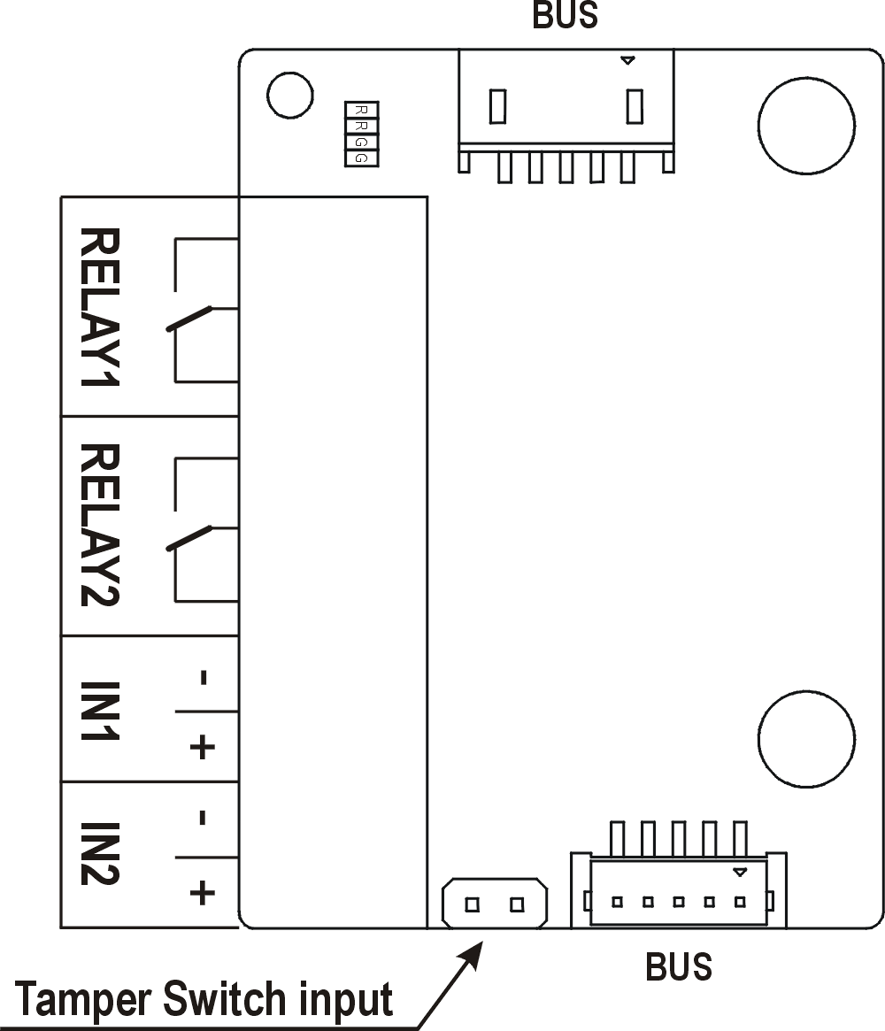 |
RELAY1 | RELAY1 terminals with accessible 30 V / 1 A AC/DC NO/NC contact |
RELAY2 | RELAY2 terminals with accessible 30 V / 1 A AC/DC NO/NC contact
|
IN1 | IN1 terminals for input in passive/ active mode (−30 V to +30 V DC) OFF = open OR UIN > 1.5 V ON = closed contact OR UIN < 1.5 V |
IN2 | IN2 terminals for input in passive/active mode (−30 V to +30 V DC) OFF = open OR UIN > 1.5 V ON = closed contact OR UIN < 1.5 V |
| TAMPER | Tamper switch (9155038) input |
5-Button
The 5-button module (Part No. 9155035) is one of the 2N® IP Verso intercom elements and is used for extending the number of buttons.
- The module contains two 2N® IP Verso bus connectors.
- These two connectors are fully interchangeable and can be used both as inputs from the main unit and outputs to other modules.
- If this module is the last one on the bus, one of the connectors remains unconnected.
- The module package includes a 220 mm long interconnecting cable.
- Nametag dimensions:
- 1 button: 52,0 (W) x 15.2 (H) mm (dimensional tolerance: +0; −0.5 mm).
- 5 buttons: 57.5 (W) x 89.0 (H) mm (dimensional tolerance: +0; −0.5 mm).
- Refer to www.2n.com for the nametag printing template.
OSDP
The OSDP module (Part No. 91550371) is one of the 2N® IP Verso modules and provides communication between a connected device (control panel, door controller) and 2N® IP Verso via the OSDP. The OSDP module provides secure sending of such access data as the access card ID or PIN code. All the inputs and outputs are galvanically isolated from the 2N® IP Verso system with insulation strength of 500 V DC.
- The module contains two VBUS connectors for device bus connection.
- These two connectors are interchangeable and can be used either as inputs from the main unit or outputs to other modules.
- If this module is the last one on the bus, one of the connectors remains unconnected.
- The module package includes a 80 mm long interconnecting cable.
The module also includes:
- Isolated OSDP bus
- Power and pairing mode signaling LED
- Tamper switch (9155038) input
 |
Having connected the OSDP module to 2N® IP Verso via the VBUS, connect the OSDP device to the module. The OSDP module uses the RS-485 bus for the interface.
Connect the OSDP device as instructed (A to B or B to A) keeping the correct order to avoid malfunction.
Caution
- When the JP2 and JP3 jumpers are mounted, strong pull-up / pull-down resistors (560 ohm) are connected to the RS-485 bus. These jumpers must be mounted / unmounted together, i.e. you cannot mount just one of them. The strong pull-up / pull-down resistors can be connected only and exclusively to one arbitrary device on the OSDP bus.
- When the JP4 jumper is mounted, a 120 ohm termination resistor is placed between the A and B wires of the OSDP bus. The termination resistors can be connected exclusively to the first and last OSDP bus modules. We recommend that these resistors are connected to the first and last modules.
Having logged in to the 2N® IP Verso web interface, use the HW / Extending Modules menu to set the following:
- Give the module a user identification (optional).
- Choose a group for access data resending, making sure that the settings are identical with those of the access readers from which the data are to be resent (card ID< PIN).
- The settings of the codes to be transmitted are optional.
- Enter the OSDP address between 0 and 126 to set the OSDP module address on the OSDP line.
- Set the communication rate in accordance with the requirements of the device to be connected.
- Enter your own encryption key into 2N® IP Verso and the opponent’s device to ensure encrypted communication.
- Enable forced encryption just for encrypted communication.
Any unencrypted communication from the OSDP device will be rejected if forced encryption is enabled.
If the OSDP device enables remote encryption key setting on a peripheral, you can use the installation mode. Once the encryption key is received, the common mode is automatically switched on. The installation mode is signaled by a LED fast blinking on the OSDP module.
Wiegand
The Wiegand module (Part No. 9155037) is one of the 2N® IP Verso intercom elements and is used for connecting an external Wiegand device (RFID card reader, fingerprint or other biometric data reader) and/or connecting the 2N® IP Verso system to an external security exchange. All the inputs and outputs are galvanically isolated from the 2N® IP Verso system with insulation strength of 500 V DC. It is necessary to feed +U IN on Wiegand OUT from the Control Panel.
- Reader – connects an external Wiegand-supporting reader. The reader sends information on the intercom card number.
- Control Panel – used for connection to the security PBX or access system to which the intercom sends information on the intercom card number.
- The module contains two 2N® IP Verso bus connectors.
- These two connectors are fully interchangeable and can be used both as inputs from the main unit and outputs to other modules.
- If this module is the last one on the bus, one of the connectors remains unconnected.
- The module package includes an 80 mm long interconnecting cable.
- The module name is configured in the Module name parameter in the Hardware / Extenders menu.
The input LED IN is addressed as follows: <module_name>.<input1>, e.g. module2.input1.
The input Tamper is addressed as follows: <module_name>.<tamper>, e.g. module2.tamper.
The output LED OUT (negated) is addressed as follows: <module_name>.<output1>, e.g. module2.output1.
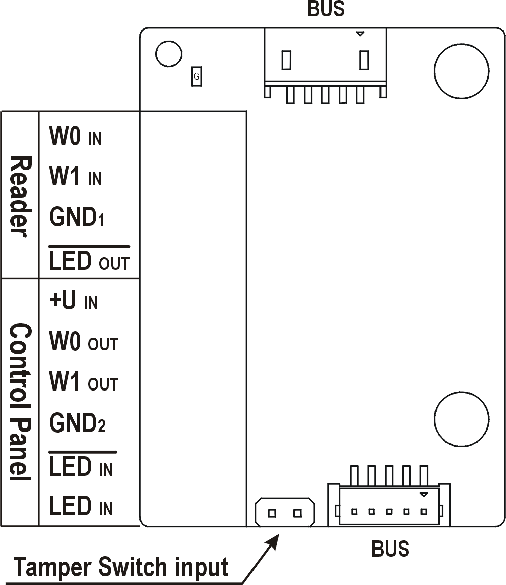 |
| Reader | W0 | Isolated 2-wire WIEGAND IN |
LED | Isolated open LED OUT switched against GND | |
| Control Panel | +U IN | +UIN (5 to 15 V DC) WIEGAND OUT power supply input |
W0 OUT, W1
GND
| Isolated 2-wire WIEGAND OUT | |
LED IN (negated) | Isolated input for open LED IN, input activated by GND2 | |
LED IN | Isolated input for open LED IN, input activated by +U | |
| G | +U | |
| TAMPER | Tamper switch (Part No. 9155038) input |
|---|
| Wiegand Input Technical Parameters | |
|---|---|
| Current | 5 mA |
| Input resistance | 680 Ohm |
| Pulse length | 50 μs |
| Delay between pulses | approx. 2 ms |
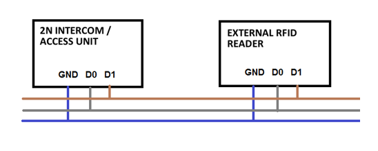 |
Recommended Wiring Diagram for Reader with Bus Driver
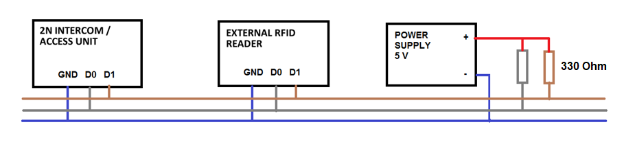 |
| Recommended Wiring Diagram for Reader with Open Collector (OC) Output |
Tamper Switch
The Tamper switch (Part No. 9155038) is one of the 2N® IP Verso intercom elements and helps secure the system against tampering.
- The module contains two switches that open whenever the front frame is removed:
- One switch leads directly to the terminal board and is designed for connection to an external security exchange (32 V DC / 50 mA max).
- The other switch, together with the I/O module (9155034) or Wiegand module (9155037), can be used for alarm signalling via the Automation interface in the 2N® IP Verso configuration.
- This module is not connected to the bus.
Caution
- Remember to purchase an I/O module, Part No. 9155034, together with the tamper switch.
 |
Tamper Switch Mounting
Blind Panel
The Blind panel (Part No. 9155039) is used for covering an empty position.
Security Relay
The 2N® Security Relay (Part No. 9159010) is used for enhancing security between the intercom and the connected electric lock. The 2N® Security Relay is designed for any 2N IP intercom model with firmware versions 1.15 and higher. It significantly enhances security of the connected electric lock as it prevents lock opening by forced intercom tampering.
 |
Function:
The 2N® Security Relay is a device installed between an intercom (outside the secured area) and the electric lock (inside the secured area). The 2N® Security Relay includes a relay that can only be activated if the valid opening code is received from the intercom.
Specifications:
Passive switch: NO and NC contacts, up to 30 V / 1 A AC/DC
Switched output:
- Where the security relay is fed from the intercom, 9 to 13 V DC is available on the output depending on the power supply (PoE: 9 V; adapter: source voltage of minus 1 V) / 400 mA DC.
- Where the security relay is fed from an external power supply, 12 V / 700 mA DC is available on the output.
Dimensions: (56 x 31 x 24) mm
Weight: 20 g
Installation:
Install the 2N® Security Relay onto a two-wire cable between the intercom and the electric lock inside the area to be secured (typically behind the door). The device is powered and controlled via this two-wire cable and so can be added to an existing installation. Thanks to its compact dimensions, the device can be installed into a standard mounting box.
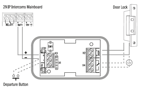
Connection:
Connect the 2N® Security Relay to the intercom as follows:
- To the intercom active output (OUT1)
Connect the electric lock to the 2N® Security Relay output as follows:
- To the switched output.
- To the passive output in series with the external power supply.
The device also supports a Departure button connected between the ‘PB’ and ‘- Helios IP / intercom’ terminals. Press the Departure button to activate the output for 5 seconds.
Status signalling:
| Green LED | Red LED | Status |
|---|---|---|
| flashing | off | Operational mode |
| on | off | Activated output |
| flashing | flashing | Programming mode – waiting for initialisation |
| on | flashing | Error – wrong code received |
Configuration:
- Connect the 2N® Security Relay to the properly set intercom switch output; refer to the Configuration Manual for 2N IP intercoms. Make sure that one LED at least on the 2N® Security Relay is on or blinking.
- Press and hold the 2N® Security Relay Reset button for 5 seconds to put the device in the programming mode (both the red and green LEDs are blinking).
- Activate the intercom switch using the keypad, telephone, etc. The first code sent from the intercom will be stored in the memory and considered valid. After code initialisation, the 2N® Security Relay will pass into the operational mode (the green LED is blinking).
Caution
- In case of resetting the factory default settings on a device with a version of firmware 2.18 or higher it is necessary to reprogram the
2N® Security Relay using the instructions above.
Connection:
 |
Tip
Video Tutorial: Security Relay Installation and Configuration