2.1 Central Unit
The 2N Lift8 system is controlled by one Central Unit (CU).
The CU contains an easily replaceable backup battery pack (lead rechargeable battery). The CU is responsible for battery charging and status monitoring. It indicates the charging state, signal strength, telephone line state, bus state core state via five color LEDs. It is also equipped with a USB interface for comfortable configuration, voice message recording and software upgrade.
The CU (version 3.0 and later) is equipped with an Ethernet port, which provides connection to the network via a fixed data connection (WAN). This data connection provides both data transmission (for remote monitoring of connected devices) and voice communication via VoIP. If the CU is equipped with an LTE/UMTS/GSM module, the Ethernet port can be used for the LAN function.
The CU can be equipped with up to two modules providing more data connection options. These modules can be factory pre-installed in the CU or supplied as separate supplementary accessories.
Description
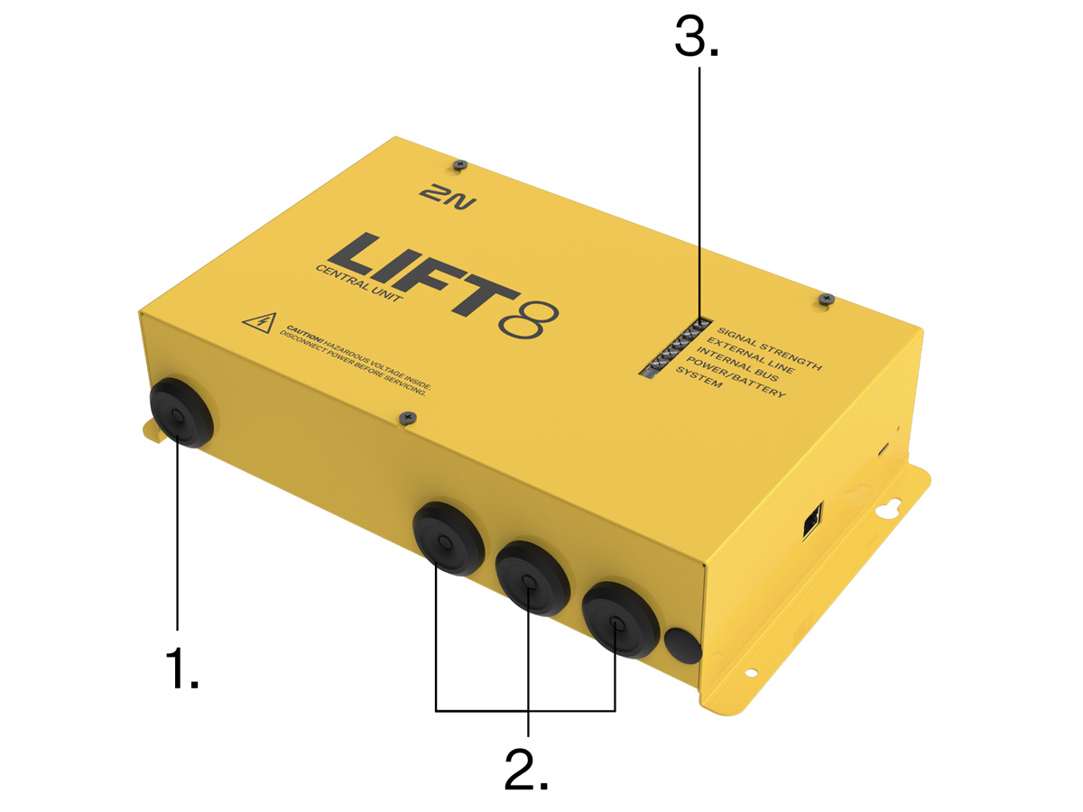
- Power cable
- Cable inputs/outputs
- LED indicators
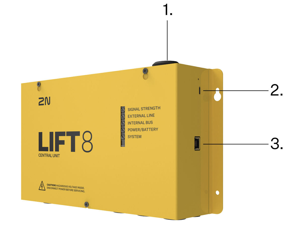
- Antenna cable input
- USB-C port
- Ethernet port
| CU LED Indicators | ||
|---|---|---|
| Signal strength | green | strong signal |
| yellow | medium signal | |
| red | weak signal | |
| no light | in case of IP/PSTN | |
| According to mobile network (valid for modules with LTE/VoIP): | ||
| 2G | light on | |
| 3G | fast flashing | |
| 4G | slow flashing | |
The signal can flicker between the individual bands (strong – medium, medium – weak). | ||
| External line | Valid for modules without LTE: | |
| green | line all right and ready | |
| green flashing | call in progress | |
| yellow | line is all right but registered in ROAMING | |
| yellow flashing (quickly) | data transmission | |
| yellow flashing (long, 3 s) | SMS in progress – sending/receiving | |
| yellow – green | call and data at the same time (only GSM/UMTS version) | |
| red flashing (slowly) | SIM not inserted | |
| red flashing (quickly) | incorrect PIN, last attempt | |
| red permanently illuminated |
| |
| External bus | Valid for modules with LTE: | |
| Relax state: | ||
| Green, light on | 4G + VoLTE available (IMS active) | |
| Yellow, light on | VoLTE unavailable and VoIP also inactive | |
| Yellow – green (1 s – 1 s) | active VoIP, i.e. SIP and 4G registration active at the same time | |
| Call: | ||
| Green, flashing (1 s – 1 s) | VoLTE | |
| Yellow, flashing (1 s – 1 s) | 2G/3G voice channel | |
| Green – yellow – no light (0.5 s – 0.5 s – 1 s) | VoIP | |
| Call: | ||
| Green, flashing (1 s – 1 s) | VoLTE | |
| Yellow, flashing (1 s – 1 s) | 2G/3G voice channel | |
| Green - yellow - no light (0.5 s – 0.5 s – 1 s) | VoIP | |
| Error states: | ||
| Red, slow flashing (1 s – 1 s) | SIM not inserted | |
| Red, fast flashing (0.5 s – 0.5 s – 0.5 s – 0.5 s ) | Wrong PIN | |
| Red, light on | Call cannot be set up / device does not work as configured (e.g. unregistered module, SIP, etc.). | |
| Internal bus | green | bus all right and in standby |
| green flashing (slowly) | voice communication (alarm or triphony) | |
| yellow flashing | Some announcers are undergoing an upgrade process, some are ready for a call. | |
| yellow – green | announcers are waiting for upgrade + call underway | |
| red | The current configuration does not correspond to the saved configuration. | |
| red flashing | sound check fail on audio units | |
| Power/battery | green | power OK, battery is charged |
| green flashing | battery charging | |
| yellow | power failure, battery in operation | |
| yellow flashing | less than 1 hour battery operation | |
| red | battery disconnected | |
| red flashing | battery defected – replace | |
| Core/system status | green | core OK |
| green flashing | system launching (the other LEDs start to flash) | |
| yellow | bootloader launching | |
| yellow flashing | internal package upgrade in progress | |
| red |
| |
| red flashing | HW has to be serviced (it is impossible to download logs and the bootloader has a fault). | |
| green – red |
| |
| turquoise | firmware upgrade | |
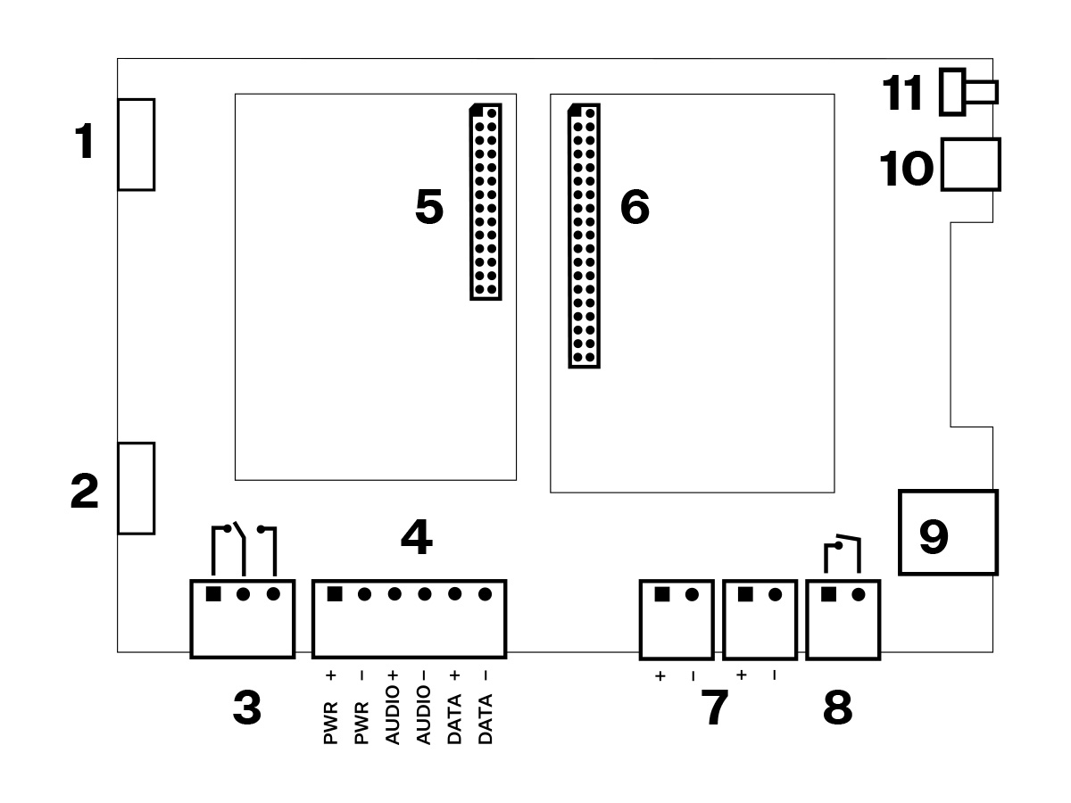
Layout of Elements on CU
- 29,2 V / 1 A
- Battery pack connection
- Elevator blocking contact (OK position)
- Main bus
- Left module bus
- Right module bus
- Audio unit bus (2 connectors)
- Tamper contact (closed when cover closed)
- Ethernet port
- USB-C port
- RESET button
Reset Button Function
- Reset equipment – press the button quickly.
- Restore factory values – press and hold the button until all the LEDs turn red. Then release the button and wait until the SYSTEM LED flashes yellow. Now press the button quickly to delete all the user settings.
- Zero backup rechargeable battery life counter – press and hold the button until all the LEDs turn red. Then release the button and wait until the POWER/BATTERY LED flashes yellow. Now press the button quickly. Perform this function after replacing the backup rechargeable batteries with new ones only!
- Check system completeness – press and hold the button until all the LEDs turn red. Then release the button and wait until the INTERNAL BUS LED flashes yellow. Now press the button quickly to make the system supervise all the installed equipment (splitters, Audio Units etc.) for proper connection and function. Refer to S. 4.8.
USB Port Connection
Recommendation
- Do not keep your PC connected for a long time unless necessary to reduce the computer damage due voltage surge from the telephone line during storms, for example.
Before You Start
CU Installation Conditions
- The Central Unit (hereinafter referred to as CU) is not intended for outdoor use.
- Do not install the CU onto vibration-producing machines.
- Install the CU vertically to allow air flow for cooling purposes (never cover the CU with any cloth or install it in another closed box).
- You may install the CU into the lift switchboard unless the temperature exceeds the acceptable limit. Remember that a higher ambient temperature reduces the life of backup rechargeable batteries in the CU.
- It is recommended that the CU should be operated in the upright position with the cable openings at the bottom. Such mounting position ensures the lowest temperatures and thus the longest life of the rechargeable batteries. Horizontal mounting is also possible. The upright position with the cable openings at the top (upside down) is forbidden!
- After mounting the CU check that the equipment is firmly fixed in place and cannot come loose and drop down into the shaft.
Product Completeness Check
Check whether the product package is complete before installation:
- 1 central unit
- 1 main bus terminal
- 4 bus connection terminals
- 4 wall plugs
- 4 wall plug screws
- 8 cable ties
- 1 battery connecting cables
- 1 brief manual
- 1 warranty sheet
- drilling template
CU Mounting
It is recommended to install the CU in a room that is secured against unauthorized persons, such as the machine room, switching station, etc. An easily accessible place is exposed to a risk of telephone line misuse or SIM card misappropriation.
The CU is mounted on a wall with the included wall plugs and screws.
Caution
- The CU is designed for multi-shaft building installations and cannot be shared by multiple buildings.
CU Electrical Installation
Putting in Operation
- Keep the CU disconnected from the mains.
- Top cover removal:
- Loosen the three screws on the upper cover of the CU.
- Slide the CU top cover so that you can remove it.
- When removing the cover, proceed with caution, be careful about the earth wire connecting the cover with the CU bottom part. Do not disconnect the wire!
- Connection of components:
- Using the slide-on terminals supplied with the device, connect the Audio Units, splitters and other components of the system with the CU. Adhere to polarity!
- Module installation:
- If the modules are not installed on the CU from the factory, mount the module. Follow the instructions provided in the User Manual for the given module.
- Connection of batteries:
- Take the rechargeable batteries out of the package and place them into the CU as instructed. Fix them into the holder and use an 8 mm spanner for tightening. Interconnect the batteries using the included cables but do not connect them to the CU
- Replace the upper cover on the CU and tighten the cover fitting screws. Doing so make sure that the earthing wire is connected to the cover!
- Reset the backup battery lifespan counter:
- Press and hold the button until all the LEDs turn red.
- Release the button and wait for the LED POWER/BATTERY to flash yellow.
- Press the RESET button briefly.
- Connect the CU to the mains supply.
Caution
- If you connect one lift shaft only, it is not necessary to connect the splitters. Use the splitters only if you want to connect 2 or more elevator shafts.
Warning
- WARNING! Live parts are exposed after the CU cover is removed!
- Be very careful and do not touch dangerous live parts!
- Never work with a switched-on CU with its protective cover off unless you are an authorized person duly trained according to Decree 50/1978 Coll.
- Never insert damaged batteries. Do not insert the batteries in the CU that might show electric or mechanical damage.
- Never use 2N Lift8 without its protective cover to avoid electric accident, malfunction due to wrong interconnection and/or 2N Lift8 electronics damage or destruction as a result of electric short-circuit or adverse environmental conditions. It is because 2N Lift8 is not protected against dangerous touch and water – IP00.
- Make sure before installation that the 2N Lift8 board is not damaged!
- Do not connect a power supply other than the allowed one to avoid electric accident or device damage.
Power Supply
- The CU is powered by 100–240 V mains power.
Rechargeable Battery Connection and State Check
- Keep the CU disconnected from the mains.
- Loosen the three screws on the upper cover of the CU.
- Move the upper cover of the CU in such a way that you can remove it.
- Proceed with caution while removing the cover: be careful about the drain wire connecting the cover with the CU bottom part. Do not disconnect the wire unless there is a reason to do so!
Interconnect the rechargeable batteries, but do not connect them to the motherboard.
Plug in the CU supply cable into a 230 V socket.
- Now interconnect the batteries with the motherboard using the FASTON cable (see the Fig. below). Maintain polarity.
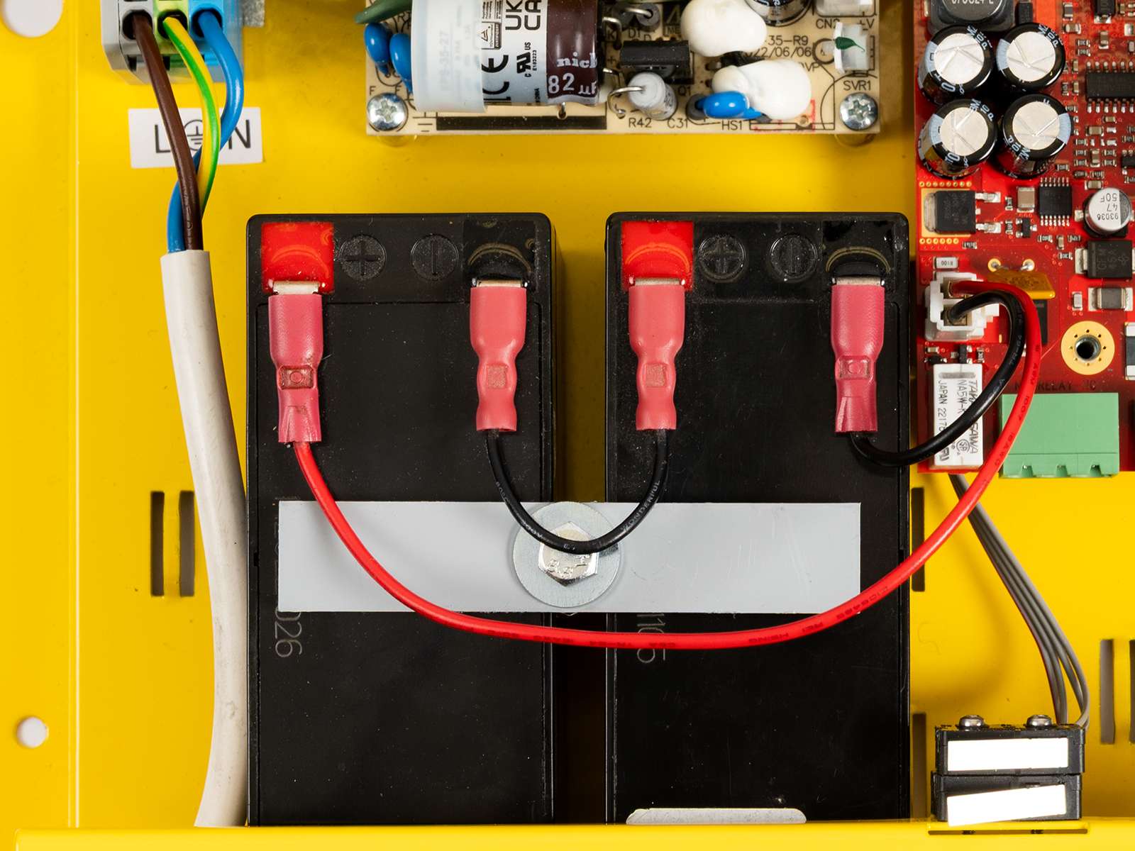
- Replace the upper cover on the CU and tighten the cover fitting screws. Doing so make sure that the earthing wire is connected to the cover!
After plugging the CU into the socket, the LED (Power/battery) should start to flash (charging). The CU charges the rechargeable batteries until fully charged. After some time, the flashing green LED (charging) should change to a permanently illuminated green LED (battery charged).
Warning
- Adhere to the polarity of the rechargeable batteries! When the polarity of the batteries is reversed, there is a danger of fire or explosion or damage to the CU electronics.
Rechargeable Batteries
Caution
- If backup rechargeable batteries are used for the 2N Lift8 power supply, the required backup of up to 1 h is guaranteed only if up to 20 audio units are connected in the system.
- The required 1h backup is not guaranteed if more than 20 audio units are installed.
- Remember to replace the batteries every two years.
Splitter – CU Bus Connection
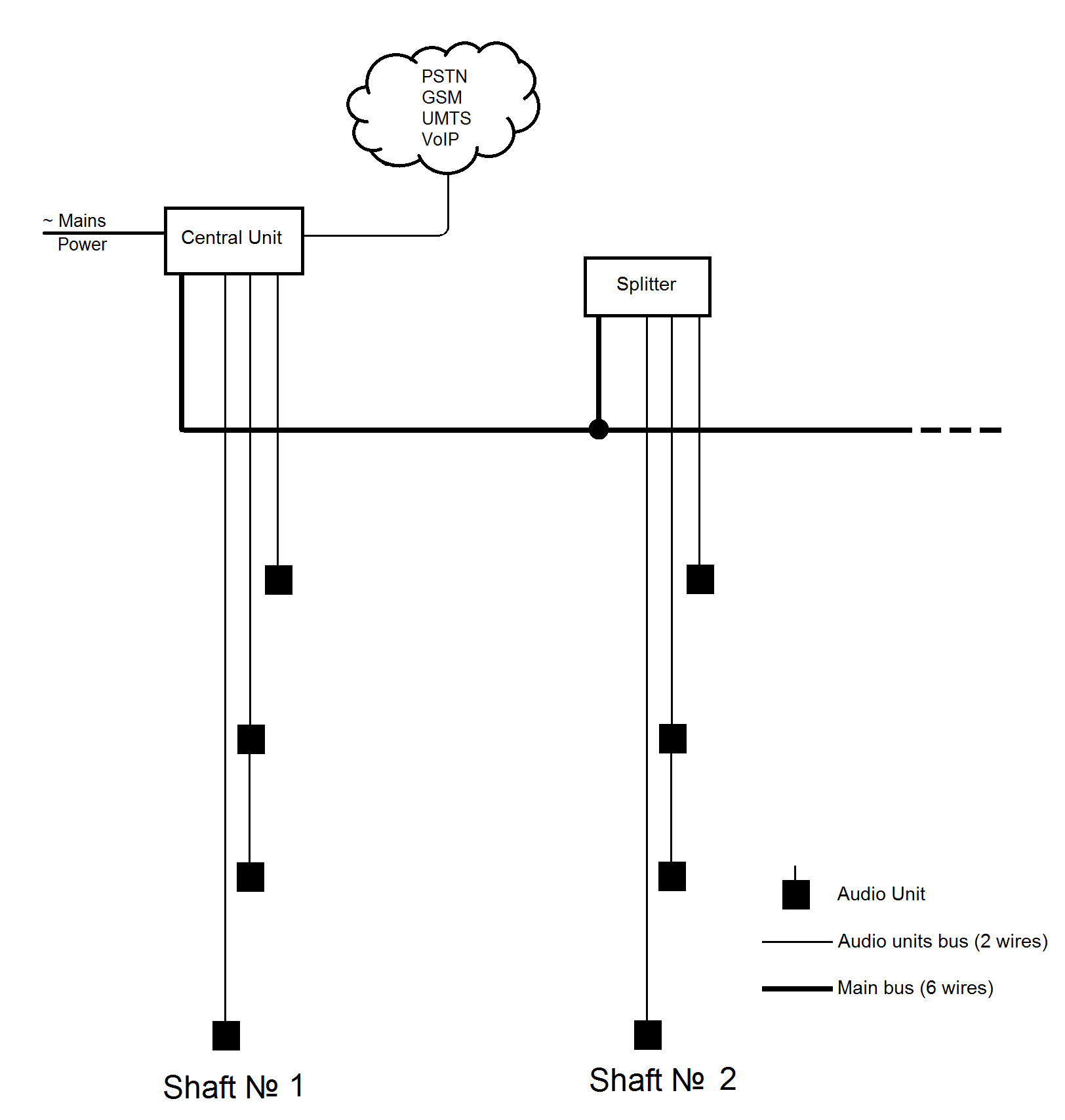 |
Interconnect the CU and splitter using a 6-wire main bus (power + − , audio + − , data + ). Mind the polarity.
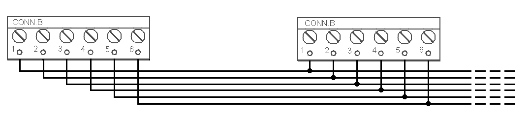 |
Main bus |
|---|
1 … Main bus power + |
2 … Main bus power − |
3 … Main bus audio + |
4 … Main bus audio − |
5 … Main bus data + |
6 … Main bus data − |
Caution
- 6-wire
- The maximum total cable length is 30 m with the cross-section of 0.75 mm2.
- For higher lengths, enlarge the supply pair cross-section: PWR (60 m – 1.5 mm2, or 100 m – 2.5 mm2).
Audio Units – Splitter (CU) Bus Connection
The Central Unit contains an internal splitter, to which up to 8 audio units can be connected. The splitter has 2 terminal boards ready for the audio unit connection.
Interconnect the splitter (in CU) and audio units using a two-wire bus. Mind the polarity.
- Remove the push-in terminal board from the audio unit connectors and connect a two-wire.
- Connect no more than 4 audio units to one terminal board.
- Maintain polarity to make the audio units work properly. Refer to the splitter and audio unit labels for correct polarity.
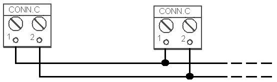 |
Audio unit bus |
|---|
1 … Bus for Audio Units + |
2 … Bus for Audio Units − |
Wiring Requirements:
- The maximum length of the two-wire circuit connected to one splitter is 600 m, including all movable parts (towing cable).
- Use unshielded wires of the cross-section of 0.75 mm2.
- Where a towing cable is used, use the neighboring cables and make sure that the nearest neighboring conductors are not a source of interference. If shielded cables are used, connect adjacent conductors to the shielding.
- If you use multicore cables, always use a pair.
Do not lead the bus in a close vicinity of power cables, via a long distance in particular.
- It is not advisable to lead the bus near the wires connected to the elevator drive.
- You can branch the bus, especially to shorten the total length of all sections.
- A shielded cable is recommended in the case of increased interference. With a shielded cable, the shielding should be continuously connected along the entire cable route. The shielding must be connected to a suitable ground point, preferably to the Central Unit grounding.
Tip
- Should bus communication problems occur, check the connection between the audio unit and the splitter (on the CU) using a two-wire lead via an alternative route far from potential interference sources.
Safety
- The bus is electrically isolated from the telephone line circuits according to the EN60950 standard requirements and its low voltage cannot cause any electrical accident.
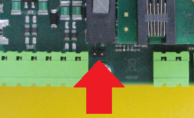
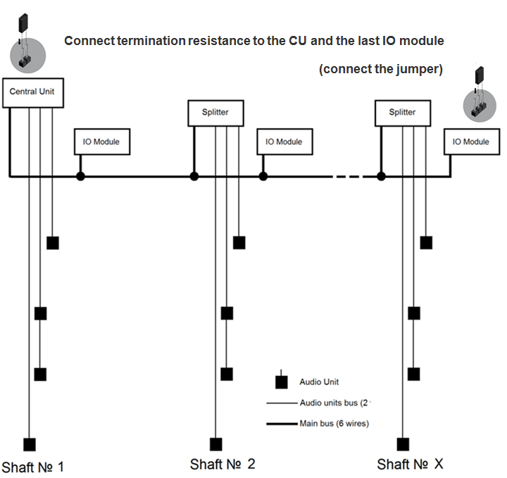
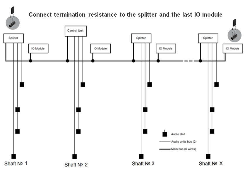
Termination Resistance
Connect the termination resistance connector to the first and last device connected to the bus: CU, splitter or I/O module.
Caution
- Find the 2-pin termination resistance connector between the main bus connector and audio unit connectors (see the figure below).
- By default, the termination resistance is connected (jumper mounted).
 |
Examples of Connection:
 |
 |
CU Connection to Telephone Network
You can connect the CU to any of the following telephone networks:
- Ethernet
- LTE(VoLTE)
- PSTN
- UMTS
- GSM
- PBX
- VoIP
PSTN
2N Lift8 works in a broad band regardless of polarity and line parameters (refer to Technical Parameters). Connect it using the enclosed cable with an RJ–12 terminal. It is the most reliable and simplest connection. The disadvantage is the operating cost (fixed fee).
Caution
- Only one CU may be connected to one telephone line and no other end telephone equipment may be connected to the line including a product through which the telephone line goes (so-called priority connection – electronic burglar alarm, e.g.).
- No dual or party lines may be used.
- No telephone “multiplugs” (adapters), even the smart ones, may be used.
- Never connect 2N Lift8 to an ISDN line.
Telephone line requirements
- The line must not be a dual or party one.
- The telephone socket and its wiring are usually the network provider's property and may not be tampered with.
Other recommendations
- Notify the telephone network provider of your 2N Lift8 installation and submit certification upon request.
- Your follow-up wiring must comply with the relevant safety regulations.
- You are recommended to secure your cabling against pirate connection (with a telephone lock, e.g.).
Connection via PBX (Private Branch Exchange)
This is the least-cost solution where a PBX and an unused PBX line are available.
PBX line requirements
- The PBX to be used must work reliably even in the case of power outage. Large PBXs are mostly equipped with a back-up power supply, smaller PBXs usually use PSTN line redirection in the event of power failure. Consult the problem with the technician responsible for your PBX. An error during power outage may result in 2N Lift8 calling an undesired station.
- Relevant call access rights have to be assigned to the PBX line to be used (use a standard telephone set to check whether the line can make outgoing calls to all the required numbers).
- While programming, enter the necessary PSTN code (typically a zero), or (preferably) make the PBX not require a prefix (so-called automatic connection to the provider's telephone line).
- To make the control room – lift calls, you have to know the extension number and how to get through to it (dial-in, DISA, operator).
- The control room – lift connection may not depend on the operator’s presence; no call forwarding to a fax/answering machine in the night mode is allowed, etc.
Other recommendations
- Make an agreement with the PBX owner regarding operating costs (2N Lift8 outgoing calls are billed at the owner‘s expense with the exception of free calls via “green lines”).
Tip
- If there is permanent manning in your building (security staff, receptionist), train the personnel how to rescue people and program 2N Lift8 to call this service.
Operation without external connection
- 2N Lift8 can be used as an intercom without an inserted SIM card or connected PSTN line during the lift fitting time. In this case do not enable the lift blocking function until the telephone line is connected.
LAN Function
Where an LTE module is available in the Central Unit, the CU Ethernet port can be switched into the LAN mode. The port is only used for connecting the network equipped devices in the LAN in this mode. The LTE module provides the VoIP connection. Set parameter 998 to switch the Ethernet port from WAN to LAN. Refer to S. 3. System Configuration for parameter settings.