2.11.1 Fireman PCB
Description: 1-Button Version
The Fireman audio unit improves the fire fighting operations by setting up top priority calls between the Fireman audio unit and the cabin and machine room audio units in one and the same lift shaft.
 |
Install the Fireman audio unit in a dedicated space that can be easily accessed by firemen.
The Fireman call has the highest priority, suspending all the other calls (refer to Function Description). It is connected with the cabin audio unit in one and the same shaft.
The Fireman call is made by a button press. The call is hands-free and terminated by pressing the button again. The maximum possible call duration is unlimited.
The Fireman call setup is signalled by the Fireman audio unit LED (mounted on the PCB or carried externally from connector 8).
The Fireman call is indicated by a flashing green LED on the machine room audio unit. The audio unit microphone is off by default. Press and hold the TRIPHONY button for 3 seconds to activate the microphone and enable communication within a fire call. Once the microphone is activated, the TRIPHONY button starts flashing.
Caution
- The Fireman calls has the highest priority and suspends all the other calls except for the Fireman call set up in another shaft.
- The Fireman call is set up by the cabin audio unit in one and the same shaft.
Button is not included.
Description: 2-Button Version (Push-To-Talk)
The Fireman audio unit improves the fire fighting operations by setting up top priority calls between the Fireman audio unit and the cabin and machine room audio units in one and the same lift shaft.
|
Install the Fireman audio unit in a dedicated space that can be easily accessed by firemen.
The Fireman call has the highest priority, suspending all the other calls (refer to Function Description).
The Fireman call is set up by pressing a lock button. The call is hands-free and terminated by pressing the lock button again. The maximum possible call duration is unlimited. ).
The Fireman call setup is signalled by the Fireman audio unit LED (blue LED shining around the button).
The two-button version allows you to connect another, Push-to-Talk button. Pressing the Push-to-Talk button silences all the other audio units connected to the fire call and the sound is only transmitted from the Fireman audio unit. When you release the Push-to-Talk button, audio transmission is re-enabled from the other audio units.
The Fireman call is indicated by a flashing green LED on the machine room audio unit. The audio unit microphone is off by default. Press and hold the TRIPHONY button for 3 seconds to activate the microphone and enable communication within a fire call. Once the microphone is activated, the TRIPHONY button starts flashing.
Caution
- The Fireman calls has the highest priority and suspends all the other calls except for the Fireman call set up in another shaft.
- The Fireman call is set up to the cabin and machine audio units in one and the same shaft.
Button is not included.
Before You Start
Fireman audio unit package contents:
- 5 straps
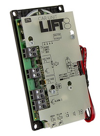
- 1 electronics board
- 3 board-slid terminals, see the photo
- 1 board-mounted jumper (defining the button version)
- 1 speaker (directly or cable connected)
- 1 microphone (directly)
- 1 printed cover
Installation Conditions
- Make sure that the panel is ready for installation, check the speaker perforation area.
- Make sure that there is 65×130×20 mm of free space behind the panel.
Mounting
Electronic Installation
Prepare the panel for installation as shown below:
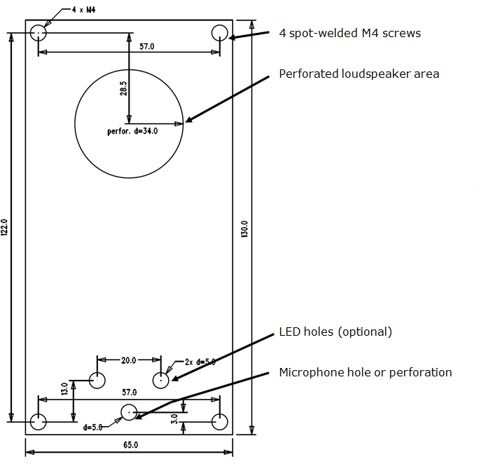 |
Figure: Mounting Hole Dimensions
To mount the unit, you need 4 electrically spot-welded (from the inner panel side) M3 or M4 screws, a sufficiently perforated speaker area and a microphone hole. If needed, a high-quality double-sided foam self-adhesive tape can be used for installation on a perfectly degreased surface.
Requirements
- The minimum distance between the speaker and microphone centres is 90 mm. A lower distance may lead to acoustic feedback. A greater distance (within the available 1m cable) does not matter.
Separate Speaker Mounting
The speaker is equipped with a cable and can be separated from the electronics by simply being slid out within the reach of the cables delivered (1 m). This option is useful where there is not enough space for the whole electronic equipment. Fit the loudspeaker according to the instructions below:
- While gluing choose such procedures or adhesives that prevent membrane damage by adhesives and volatile substances, or heat.
- We recommend you to keep the speaker sealed to eliminate vibrations and ensure electric insulation.
Frequently Asked Questions Concerning Speaker
- Can I use a speaker of my own?
Yes, but keep the impedance of 64 Ω. Doing this, however, you assume responsibility for sufficient volume and frequency range.
- Can I use a longer cable for the speaker?
You can use a longer cable for the speaker, but not for the microphone.
Electric Installation
Description of Terminals, Connectors and Jumpers
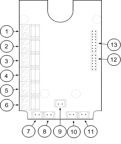 |
Figure: Terminals, Connectors and Jumpers
Terminals | Connectors | |||||||||
|---|---|---|---|---|---|---|---|---|---|---|
1 | Audio unit bus | 7 | Unconnected | |||||||
2 | Unconnected | 8 | LED | |||||||
3 | Unconnected (1-button version) Fireman call activation – with detent (2-button version) | 9 | Microphone connector (optional) | |||||||
4 | Unconnected | 10 | Induction loop connector | |||||||
5 | Activation/Deactivation – without detent (1-button version) Push to talk – without detent (2-button version) | 11 | Speaker connector | |||||||
6 | Unconnected | 13 | Servicing connector | |||||||
Configuration Jumpers | Two LED Indicators (from the other side) | |||||||||
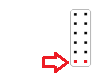
12 |
The lower pin defines the button count
| 1. (yellow) | Shining – active Fireman call Flashing – Push to talk (for 2-button versions only) | |||||||
2. (green) | ||||||||||
Note
- If an external LED is connected to connector 8, the LED 1 indicator will not be shining.
Bus Connection
Pull the terminal out of connector 1 – Audio units bus, connect the bus audio units wires and replace the terminal to connector 1. Mind the polarity.
Warning
- The audio unit is intended for 2N Lift8 audio unit bus connection exclusively. Do not connect it to other wires to avoid its damage or destruction.
- Maintain polarity while connecting the audio unit to avoid audio unit error.
Caution
- The audio unit is powered via a 2-wire bus. Disconnection of these wires results in the audio unit switch-off.
- Proper polarity (+ -) is shown on the cover of audio unit.
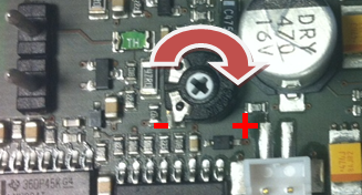
Volume Setting
Loosen the four screws slightly and move the cover downwards. Remove the cover. Use the trimmer in the lower part of the electronics to adjust the volume (see the figure below).
 |
Caution
- Use the trimmer to set the best acoustic properties while eliminating feedback.