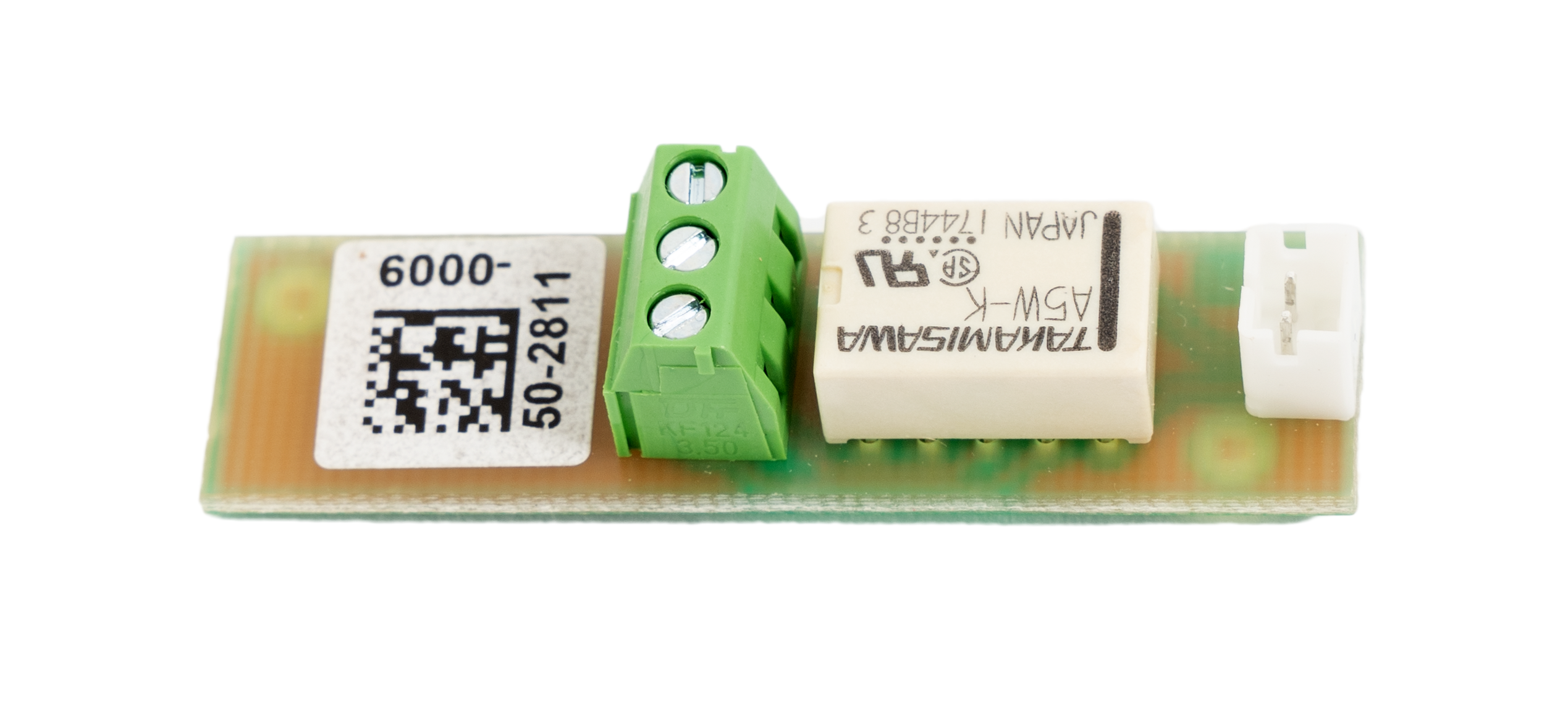
2.8 2N® LiftIP 2.0 Relay Extender
Description
The 2N® LiftIP 2.0 Relay extender extends 2N® LiftIP 2.0 to include one additional output. The relay output type makes it posible to switch both voltage polarities. According to the activation type, the blocking output opens/closes if it is impossible to set up an alarm call from 2N® LiftIP 2.0 (if there is no number in the Alarm button configuration or no SIP server registration except when Direct call is set for the Alarm button).
Wiring Diagram
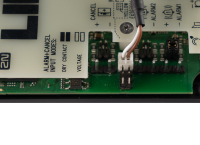
The 2N® LiftIP 2.0 Relay extender is connected into the RELAY connector (see 2.5 Description of LEDs, Terminals, Jumpers and Connectors).
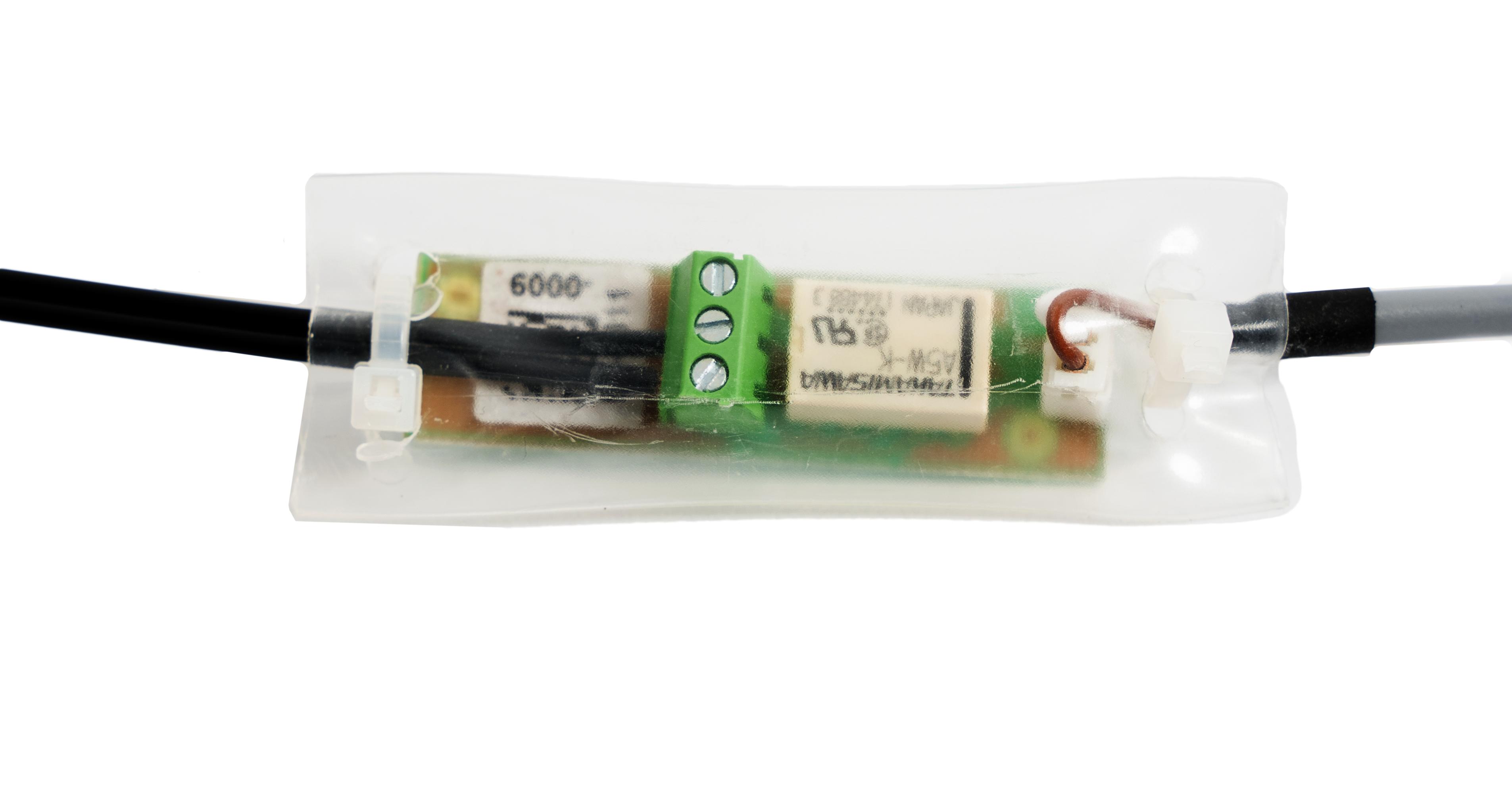
Interconnect 2N® LiftIP 2.0 and 2N® LiftIP 2.0 Relay extender using a cable.
Note
- The relay output error state is signaled in the same way as if the device was disconnected from the power supply. The relay output is without voltage.
Warning
- Disconnect 2N® LiftIP 2.0 from the power supply (10–30 V DC or PoE) while connecting 2N® LiftIP 2.0 Relay extender.
- To protect the circuits against short circuit with other conductive objects, put 2N® LiftIP 2.0 Relay extender into an insulation tube and secure it with cable ties before installation!
- Keep the proper connection (yellow wire).
- A wrong connection may damage the module.
Technical Parameters
| Output | |
|---|---|
| Maximum switching power | 15 W |
| Maximum switching voltage | 30 V |
| Maximum switching current | 2 A |
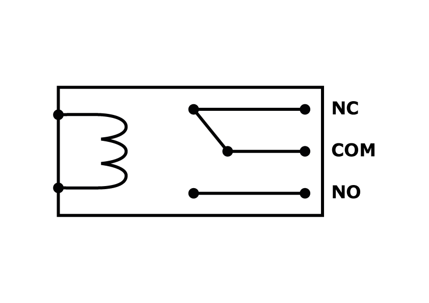
| Output Type | galvanically isolated, enables both voltage polarities to be switched |
Diagram | |
Example: Use the COM and NO contacts to make the relay connect the circuit after voltage is carried to the coil. | |