2.3 Mounting
Safety Precautions
Caution
- Make sure that the position, appearance and marking of the communicator controls (ALARM button, e.g.) are in accordance with the applicable lift standards.
Before You Start
Installation Conditions
- Make sure that the lift panel is ready for installation, including speaker perforation.
- Make sure that the panel includes the required elements:
- ALARM button;
- illuminated pictogram Request received;
- illuminated pictogram Connection established.
- Make sure that the positions of these pictograms are in accordance with the applicable regulations.
- Make sure that there is a free space of 65 (W) x 130 (H) x 25 (D) mm at least behind the panel.
2N® LiftIP Position
2N® LiftIP can be mounted in any position as required. The optimum position for
2N® LiftIP is approximately on the level of an adult‘s mouth. Install 2N® LiftIP on a place where any contact of the operating personnel with the device is eliminated (refer to Safety Precautions).
Caution
- Installing electronics without the mounting panel is not recommended as the panel is used as electric insulation and the manufacturer cannot guarantee safety if the panel is not used.
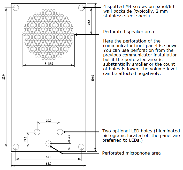
2N® LiftIP Electronics Panel Mounting
What you need to mount the electronics panel onto the lift button panel:
- four 57 (W) × 122 (H) mm spot-welded M4 screws;
- sufficiently perforated speaker area (may be larger than as shown in the figure but may never exceed the panel size to avoid acoustic fault);
- microphone hole;
- two LED holes if necessary.
Mounting Drawing for 50 mm Speaker Installation
 |
Caution
- Make sure that microphone hole is sealed properly to record only sounds from the cabin instead of the noise from the shaft or space behind the panel.
Off-Panel Microphone Mounting
By default, the microphone is mounted directly on the 2N® LiftIP printed circuit (see the drawing for its position). If required, the microphone can be supplied with a cable mounted on a 25mm diameter holder with self-adhesive foil. This allows you to mount the microphone behind any lift button panel hole of the minimum diameter of 3 mm or a group of holes of the same total area. Switching to an external microphone is automatic (its connection is detected). The minimum centre-to-centre distance between the speaker and microphone is 90 mm. A shorter distance may result in acoustic feedback. A longer distance does not matter.
Warning
- Always make sure that the microphone hole is sealed properly against noise from the gap between the lift cabin wall and mounting panel. The microphone should record sounds from the cabin instead of noise from the shaft or the space behind the panel where 2N® LiftIP is installed !
Off-Panel Speaker Mounting
By default, the speaker is mounted on a panel and equipped with a 1m cable. You can also remove the speaker from its panel bed and place it separately. By default, the speaker is mounted on a panel and equipped with a 1m cable for additional amplifier installation. You can also remove the speaker from its panel bed and place it separately. In that case, respect the electric safety precautions, see below!
Caution
- Installing the speaker separately, make sure that the grid does not surpass the speaker dimensions in any case to eliminate the acoustic fault between the speaker front and back sides!
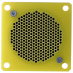
Accident Risk
- Mount the 50mm speaker on an insulating (non-metallic) surface only or require an external panel (not included in the delivery), see the figure below.
 |
Caution
- We do not recommend you to install the microphone and speaker on completely different cabin sites (ceiling and wall, e.g.) as the users should find the speaker (grid/perforation) easily and then speak into the microphone near it.
Caution
- You are recommended to turn down the speaker volume to minimise the microphone-speaker feedback (echo).
How to Achieve Ideal Acoustic Properties
To ensure the minimum acoustic pressure according to the EN 81-28:2015 standard requirements, the holes in the communicator speaker covering panel should occupy 20 % of the speaker area at least and be placed above the speaker.
Make sure that the speaker and the microphone fit tightly to the covering panel. If this is impossible due to panel surface unevenness, we recommend you to seal the speaker to avoid speaker sound leakage into the space behind the panel. A correct microphone installation is crucial for high-quality audio transmission and good intelligibility.
Try to minimise the acoustic feedback between the speaker and the microphone during installation.
Indicator Mounting
There are three types of 2N® LiftIP state indicators:
- Illuminated pictograms are part of the cabin control panel.
- LEDs directly on the 2N® LiftIP electronics plus optional light guides conducting light to two panel holes.
- Two optional LEDs can be connected to 2N® LiftIP via a cable.
Note
- Make sure that your indicators comply with the applicable legal regulations. However, no indicators are necessary for the 2N® LiftIP communication.