2.8 IO Extender
Description
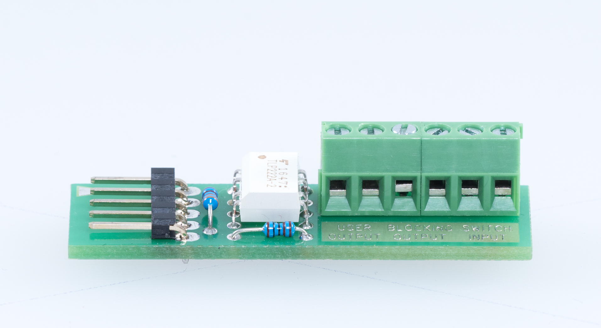
The IO extender helps you extend 2N® LiftIP to include 1 input and 2 outputs.
The input is used for rescue mode termination (as set in parameter 966–1 or 3) and ALARM 2 call setup. The input is N/O contact controlled.
- A short press (approx. 100 ms) sets up a call to the phone number set in parameters 021–026.
- A long press (approx. 3 s) cancels the rescue process.
The Blocking output closes if 2N® LiftIP cannot set up an alarm call (due to an absence of Proxy registration or no number in the Alarm button memory).
The User output is not used for the time being.
 |
Connection
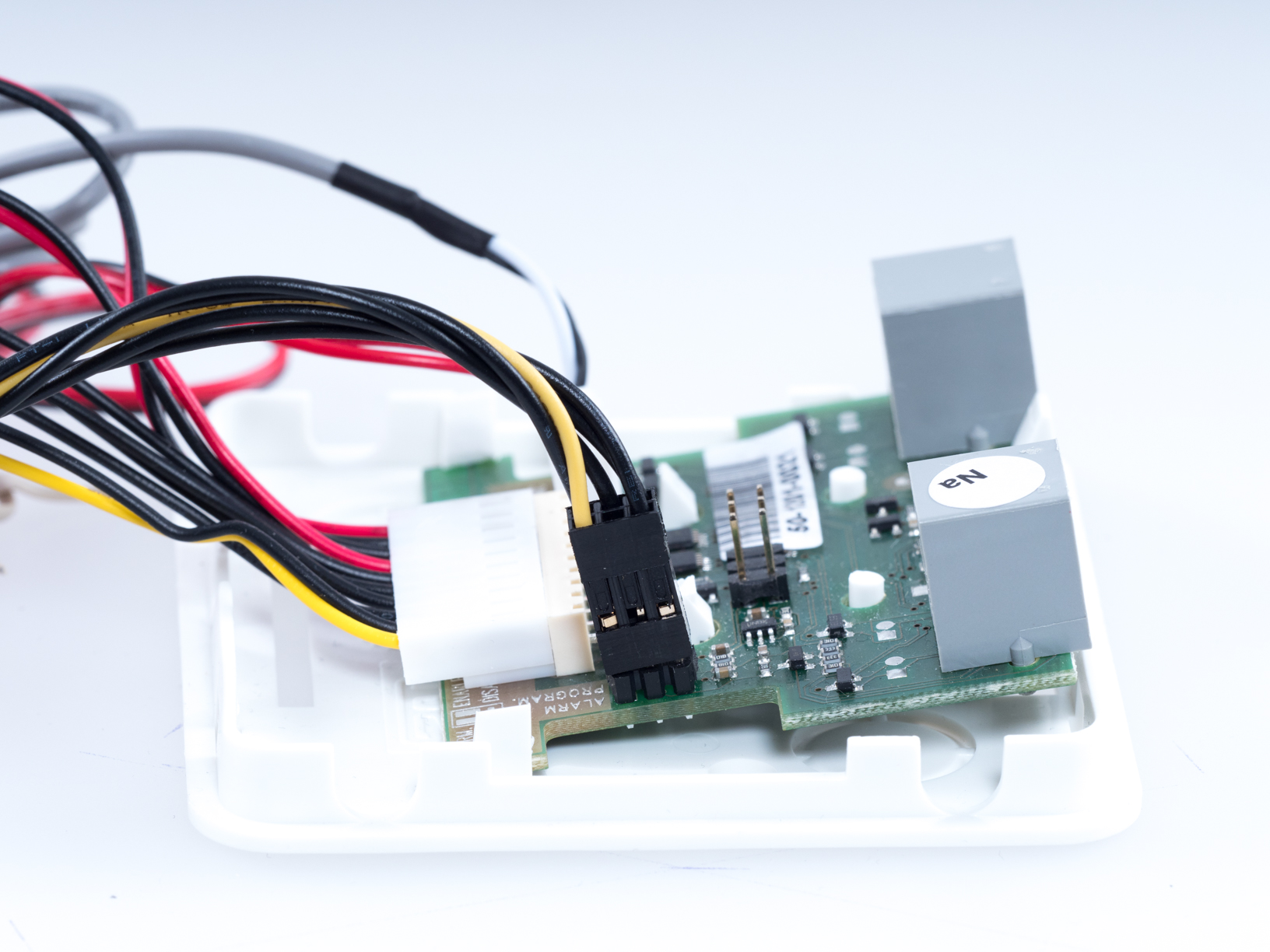
Connect the IO extender to the Extender connector (refer to Subs. 2.5). The Voice Alarm Station (VAS) can also be connected to this connector.
 |
 |
| User output | Blocking output | Switch input |
|---|---|---|
Unused | Activated at lift blocking | N/O contact connection for rescue mode end |
Warning
- Disconnect LiftIP from the power supply while connecting the IO extender (DC 10–30 V or PoE).
- Make sure that all the pins are inserted in the 6-pin connector correctly while connecting the IO extender.
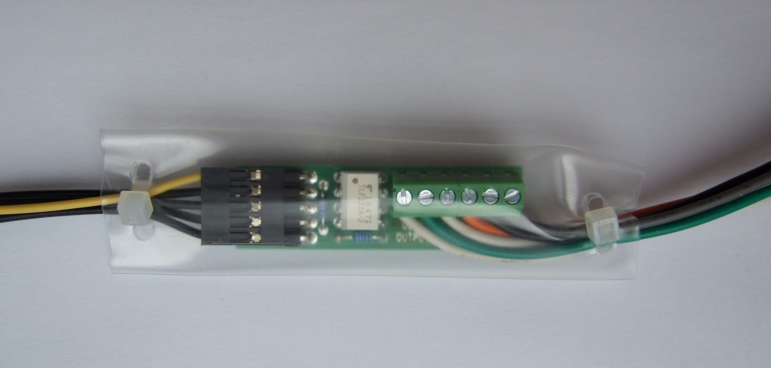
- Keep the correct connector wiring (yellow wire - see the figure below).
- Wrong wiring may lead to a module damage.
- Put the IO module in the attached insulation tube and tighten with cable ties before installation to protect the circuits against short-circuit with other conductive objects!
Connection via Voice Alarm Station
You can also connect the IO extender via a Voice Alarm Station (VAS). Insert the VAS in the Extender connector (refer to Subs. 2.7 of the VAS manual).
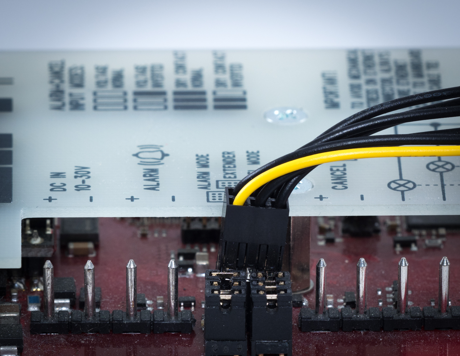
Connect the IO extender to the VAS switch. Put the connector on the Alarm IN/Program jumper (see the figure below).
 |
Warning
- Disconnect LiftIP from the power supply while connecting the IO extender (DC 10–30 V or PoE).
- Make sure that all the pins are inserted in the connector correctly while connecting the IO extender.
- Keep the correct connector wiring (yellow wire - see the figure below).
- Wrong wiring may lead to a module damage.
Technical Parameters
| Input | |
|---|---|
| Input type | contact controlled, galvanically non-isolated |
Warning
- Never connect any voltage sources to the input. You can only connect the N/O contact that is not connected to any other circuit.
| Outputs | |
|---|---|
| Maximum load | 60 V / 500 mA |
| Insulation strength | 500 V |
| Output type | open at relax, galvanically isolated, can switch both voltage polarities |