2.3 Installation Conditions
Make sure that the following 2N® Indoor Talk installation conditions are met:
- There must be enough space for the device installation.
- The device is designed for vertical wall mounting (perpendicular to the floor) in the height of up to 120 cm above the floor. If necessary, operate the device in a position other than as aforementioned for a short time only, for quick testing purposes in a servicing centre, for example.
- Exceeding the allowed operating temperature may not affect the device immediately but leads to premature ageing and lower reliability. Refer to S. 5. Technical Parameters for the acceptable range of operating temperatures and relative humidity values.
- The device is not designed for environments with increased vibrations such as means of transport, machine rooms and so on.
- The device is not intended for dusty environments and places with unstable humidity and abrupt temperature changes.
- The device may not be exposed to aggressive gas, acid vapours, solvents, etc.
- The device is not intended for direct connection into the Internet/WAN.
- The device must be connected to the Internet/WAN via a separating active network element (switch/router).
- The device is designed for indoor use. It may not be exposed to rain, flowing water, condensing moisture, fog, etc.
- The device cannot be operated on places exposed to direct sunshine and near heat sources.
- Keep some free space above and below the device to allow air to flow and conduct heat away.
- No strong electromagnetic radiance is allowed on the installation site.
- The VoIP connection must be configured properly according to the SIP and other VoIP recommendations.
- It is recommended that the power adapter be connected to the mains via a UPS and reliable overvoltage protection.
Power Supply Connection
You can feed 2N® Indoor Talk as follows:
- Use a 12 V / 1 A DC power adapter connected to the backside terminal board.
- Use an Ethernet cable connected to a PoE supply or PoE supporting Ethernet switch/router.
PoE Supply Connection
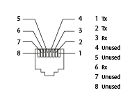
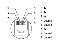
Use a standard straight RJ-45 terminated cable to connect 2N® Indoor Talk to the Ethernet. The device supports the 10BaseT and 100BaseT protocols. The Ethernet connection state is indicated by the ![]() symbol (hung-up receiver). If the symbol flashes, the device is disconnected from the network.
symbol (hung-up receiver). If the symbol flashes, the device is disconnected from the network.
Caution
- Factory reset results in a change of the Ethernet interface configuration!
- A defective Ethernet cable may lead to a high packet loss in the Ethernet and subsequent instability and poor call quality!
Warning
- Do not connect an external power supply if PoE is used and vice versa.
- Connection of a defective or improper power supply may lead to a temporary or permanent device failure.
| Ethernet cable connector | Ethernet socket | ||
|
|
Firmware Upgrade
We recommend you to upgrade the 2N® Indoor Talk firmware during installation. Refer to www.2n.com for the latest FW version. Refer to 3.2.5 System for the firmware upgrade procedure.