2.2 Brief Installation Guide
 |
 |
Remove the cover from the walled-in 2N® Indoor Talk flush mounting box. Remove the pre-prepared cabling, UTP cable, doorbell twin cable and power supply cable. Shorten the cables to 150 mm or less as required. Connect the doorbell twin cable or power supply cable to the connector provided. Crimp the RJ-45 connector onto the UTP cable.
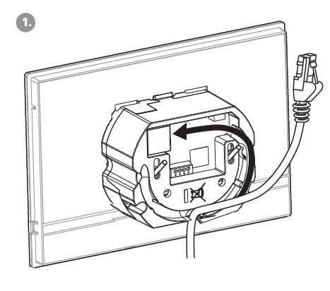
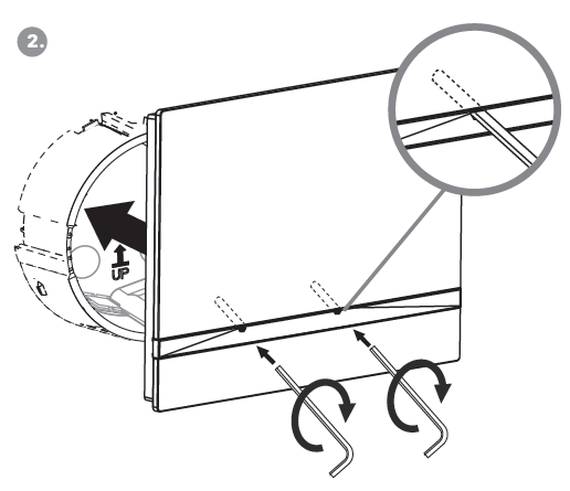
Take 2N® Indoor Talk and lean its bottom edge against the wall below the flush mounting box. First plug the green doorbell/power connector and then the LAN connector. Put the cables carefully in the pre-drilled 2N® Indoor Talk back slot to prevent them from blocking any horizontal levelling movement during the final installation stage. Insert 2N® Indoor Talk in the flush mounting box making sure that it clicks onto the levelling pins, which allow for a 5–6° inclination on either side for accurate horizontal levelling. Apply the box screw nuts with the hexagon key wrench provided. Level 2N® Indoor Talk with a water level and tighten the screws gently. Now 2N® Indoor Talk is ready for basic operation.
Alternatively, install the device in a stand. Within installation preparations, take out the pre-prepared cabling, UTP cable, doorbell (twin) cable and power supply. Shorten the cables to the required length. Connect the doorbell twin cable or power supply into the connector. Crimp an RJ-45 connector onto the UTP cable. See the figures and installation instructions below.
- Pull the cables through the hole in the stand bottom.
- First connect the green power supply/doorbell connector to the device. Then connect the LAN connector. Install the cables carefully into the pre-prepared groove on the back side so that they cannot get in the way and prevent free movement in the final installation stage.
- Put the device on the stand making sure that it fits onto the centering pins. The aligment of the stand bottom edge and the device bottom strip means that the device is installed propely. Fit the device to the stand by tightening the screws through the front side. Use a hexagon key wrench for tightening. Tighten the screws gently.
- Remove the protective foil from the antislip belts on the stand bottom and install the device on a selected place. Now the device is ready for basic operation.
2N® Indoor Talk consumption with variable power supplies:
| Power supply must comply with PS1 class output | |
|---|---|
| Supply type | Consumption |
| PoE, IEEE 802.3af | 12 W |
| 12 V / 1 A | 12 W |
Warning
- Do not connect any external power supply if PoE is used and vice versa.
- If you use a power adapter other than the recommended one, do not exceed the 12 V rated supply voltage. Also check the supply voltage polarity. Higher voltage values or misconnections may result in an irreplaceable device damage.