2.3 Brief Installation Guide
SIM Card Inserting/Removing
For the correct handling of SIM cards refer to the SIM Card Placement subsection.
Caution
- Make sure that the GSM gateway is off before inserting and removing SIM cards to avoid the GSM/UMTS module damage.
Installation Conditions
The following installation conditions have to be met for proper installation:
- 2N® VoiceBlue Next is to be installed on a site with enough free space.
- 2N® VoiceBlue Next can be mounted on a vertical surface (2-channel version), or on a horizontal surface or into a system rack (4-channel version). It is possible to operate 2N® VoiceBlue Next in another working position too, e.g. on a desk, for a short time for servicing and testing purposes, for example.
- Any excess of the allowed working temperature may not affect the 2N® VoiceBlue Next function immediately but may result in faster ageing and lower reliability. For the allowed working temperature and humidity ranges refer to S. 5
- 2N® VoiceBlue Next is not designed for high-vibration environments such as means of transport, machine rooms, and similar.
- 2N® VoiceBlue Next is not designed for dusty environments or places exposed to high humidity and temperature changes.
- 2N® VoiceBlue Next may not be exposed to aggressive gases, acid and solvent vapours, and so on.
- 2N® VoiceBlue Next is intended for indoor use. It may not be exposed to rain, flowing water, condensing moisture, fog, and so on.
- 2N® VoiceBlue Next may never be exposed to direct sunshine or placed close to heat sources (radiators).
- A sufficient clearance must be kept over and under 2N® VoiceBlue Next for cabling and air flow to carry off the heat.
- A sufficient GSM/UMTS signal intensity has to be provided for 2N® VoiceBlue Next.
- An adequate capacity of the GSM/UMTS network has to be ensured (no BTS overload). Remember that multiple GSM gateways used in one location may overload the base transceiver station (BTS) you are currently logged in to. This may lead to a permanent or occasional rejection of GSM/UMTS calls!
- No strong electromagnetic radiation is allowed on the 2N® VoiceBlue Next installation site.
- No strong electromagnetic reflections are allowed on the 2N® VoiceBlue Next antenna installation site.
- An inappropriate location of 2N® VoiceBlue Next or its antenna close to television, broadcasting and/or other rf-sensitive sets may impair the function of these sets.
- Being a source of radio frequency emissions, the 2N® VoiceBlue Next antenna should not occur in the close vicinity of the human body. The health hazard is higher than with mobile phones as, generally, gateways shared by multiple users show a very high traffic.
- Make sure that the VoIP connection has been configured properly according to the SIP and other VoIP recommendations.
- It is recommended that the power supply adapter should be connected to a network with a UPS back-up and due overvoltage protection.
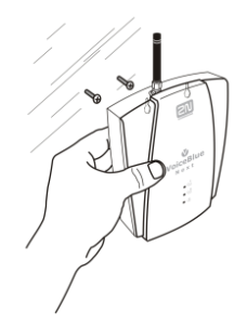 |
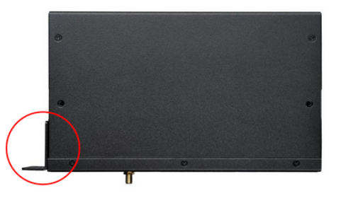
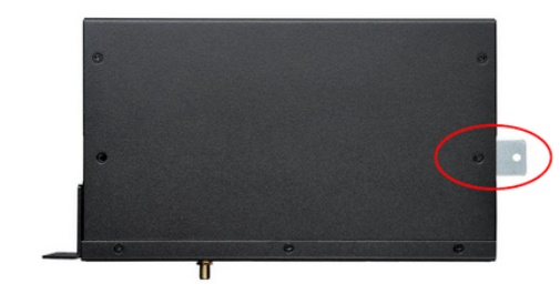
Wall Mounting (2-Channel Version)
Follow the instructions below to wall mount 2N® VoiceBlue Next:
- Drill two screws into the wall in a relative distance matching the wall mounting holes in the 2N® VoiceBlue Next rear. The maximum screw head – wall distance is 5mm.
- Hang the 2N® VoiceBlue Next unit onto the pre-drilled screws.
Caution
- Do not open the GSM gateway during wall mounting to avoid product damage and subsequent warranty invalidation!
- The screw head – wall distance must allow for simple handling such as removing from the wall.
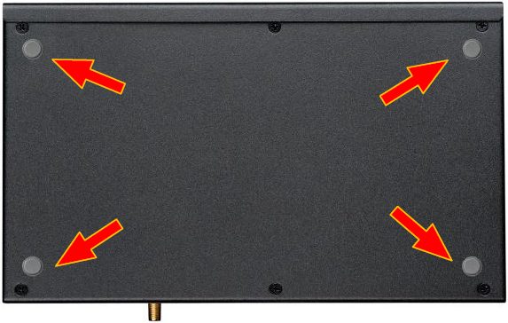
Horizontal Mounting (4-Chanel Version)
2N® VoiceBlue Next is ready for mounting on a horizontal support. You can stick rubber feet (included in the delivery) on the device if necessary. Follow the instructions below:
- Put the GSM gateway carefully on a stable horizontal support with its bottom side up.
- Stick the rubber feet into the corners as shown below.
- Place the device on a stable horizontal support.
 |
Caution
- Refer to the Proper Location subsection for correct placing!
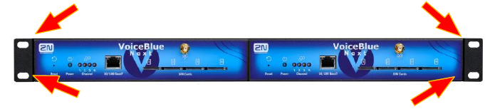
System Rack Mounting (4-Channel Version)
2N® VoiceBlue Next can be mounted into a system rack. Purchase the rack accessories separately under Part No. 5051099E. The accessory pack includes the following components:
Components | Pieces |
|---|---|
Short wing | 2 |
Long wing | 1 |
Rear connecting plate | 1 |
Upper connecting plate | 1 |
Mounting screws | 12 |
Rack screws | 4 |
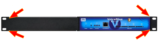
Single Mounting
Follow the instructions below to mount a single unit into a system rack:
1. Fit the rack wings to the right and left sides using four screws for each wing (included in the package). The positions of the long and short wings are optional and depend on the installation site conditions.
 |
 |
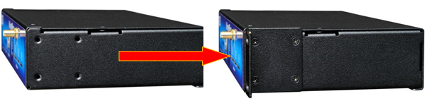
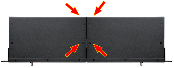
Pair Mounting
Follow the instructions below to rack mount two GSM gateways into one 1U place:
1. Put the GSM gateways next to each other making their sides touch each other. Fit the short wings (included in the package) onto the free gateway ends with the screws enclosed
 |
 |
 |
 |
 |
Caution
- The rear and upper connecting plates have different holes – the upper plate holes are larger and without threading.
- Make sure that the plate does not get into the device to avoid electric short-circuit inside the GSM gateway.
- Leave 2 cm free space at least over and under the GSM gateway for better ventilation (airflow)!
Power Supply Connection
Use only the power supply adapter included, or, with the power over Ethernet, a certified PoE adapter to feed the gateway. Make sure that the electric distribution network voltage is in compliance with the data on the supply adapter plate before plugging the adapter. First plug the supply adapter into the mains socket and only then connect the adapter connector to the gateway. Refer to the status indicators.
Warning
- Connecting a defective or inappropriate power supply adapter may lead to a temporary or permanent 2N® VoiceBlue Next error!
- Never connect 2N® VoiceBlue Next using the PoE and a local adapter at the same time to avoid permanent 2N® VoiceBlue Next malfunction!
- Check whether the antenna is connected before plugging the adapter. Feeding the device without antenna connection may result in the GSM module transmitter damage.
Antenna Connection
2N® VoiceBlue Next is equipped with a SMA female antenna connector for all the GSM/UMTS modules. The external antenna should always be installed vertically on a site with a good wireless signal.
Warning
- Tighten the antenna connector gently with your hand – never use a wrench!
- Being a source of radio frequency emissions, the 2N® VoiceBlue Next antenna should not occur in the close vicinity of the human body. The health hazard is higher than with mobile phones as, generally, gateways shared by multiple users show a very high traffic.
Note
- The antenna has a sufficient gain for a trouble-free operation under normal conditions. If the signal is poor or you want to place your antenna separately from 2N® VoiceBlue Next, you can use an antenna with an SMA-connector terminated cable. The antenna should be mounted vertically.
- Refer to the Technical Parameters section for the antenna and cable parameters.
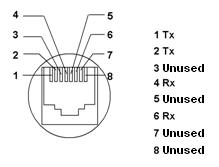
Ethernet Cable Connection
To connect 2N® VoiceBlue Next into an Ethernet network use a standard straight cable terminated with RJ-45 connectors (included in the package). The GSM gateway supports the 10BaseT and 100BaseT standards, the Ethernet connection status is indicated by the status LED indicators located on the RJ-45 connector (refer to Subs. 2.1 for details).
For the Ethernet interface factory settings for 2N® VoiceBlue Next refer to Subs. 2.2.
Caution
- Resetting factory values results in a change of the 2N® VoiceBlue Next Ethernet interface configuration!
- Using a defective Ethernet cable may lead to a high packet loss rate in the Ethernet network and subsequent instability and poor quality of all GSM/UMTS calls!
 |
Antenna Splitter
The antenna splitter is a passive component that combines multiple GSM/UMTS channels into one antenna. In 2N® VoiceBlue Next, it combines two/four antennae into one. The antenna splitter is placed in the installation box. It is a passive element – it has a characteristic signal attenuation value that the antenna connected must compensate. No antenna splitter is used for one-channel 2N® VoiceBlue Next gateways.
Licence Restrictions
2N® VoiceBlue Next may contain time limited software licences. See p. for more information.
Firmware Upgrade
Please upgrade the 2N® VoiceBlue Next firmware before installing the system. Check the www.2N.cz web sites for the latest firmware for this gateway type.
Warning
- Use the firmware certified for this gateway type only! Any other firmware type may damage 2N® VoiceBlue Next irreversibly!
Follow the instructions below to download firmware easily using the gateway web interface:
- Connect your PC and the gateway into the Ethernet network.
- Open the web browser (MS Internet Explorer 9 and higher or Mozzila Firefox 4 and higher are recommended).
- Enter the http://IP_address to register at the web interface.
- Click on Management / Firmware update, then on Browse and select the new firmware file.
- Click on the Download firmware icon in the lower part of the web page.
- 2N® VoiceBlue Next will upgrade the firmware automatically.