5.3.1 Switches
 |
Switches provide a very flexible and efficient control of such peripherals connected to the 2N device as electric door locks, lighting, additional ringing signalling, and so on. 2N device allows you to configure to 2 independent all-purpose switches.
A switch can be activated by:
- entering a valid code via the numeric keypad,
- tapping a valid RFID card on the reader,
- a predefined delay after another switch activation,
- by a time profile *),
- receiving an HTTP command from another LAN device,
- the Action.ActivateSwitch action via Automation *).
Switch activation can be blocked by an appropriately selected time profile if necessary.
Caution
- The options marked with *) require their respective active licences.
Switch locking and hold
The switch activation conditions are modified using two functions: switch locking and switch hold. If a switch is locked, it is permanently deactivated and cannot be operated until unlocked (locked has a higher priority than held – in case the switch is locked and held simultaneously, locking is applied). If held, the switch is in the activated state and cannot be operated until released.
Switch locking and holding can be controlled by time profiles among others. It is not recommended that a time profile be used for the locking function (the time-profile based lock control is present in the device for legacy switch compatibility reasons) because this case results in switch unlocking at the end of the time profile despite manual switch locking.
The current combination of these two functions is shown by the Current switch function parameter (Normal – lock and hold are off; Held – lock is off and hold is on; Locked – lock is on regardless of the hold setting).
Check after restart whether or not the lock/hold is controlled by a time profile. If so, the given function is activated/deactivated according to the time profile setting. If not, the last locking state before the device power off is set, or hold is set to inactive (the switch is not held).
If a switch is active, you can:
- activate any logical output of the device (relay, power output).
- activate the output to which the 2N IP Security Relay module is connected.
- send an HTTP command to another device.
The switch can work in the monostable or bistable mode. The switch is switched off after a timeout in the monostable mode and switched on with the first activation and off with the next activation in the bistable mode.
The switch signals its state by:
- a programmable beep.
- a LED indicator if available in the model.
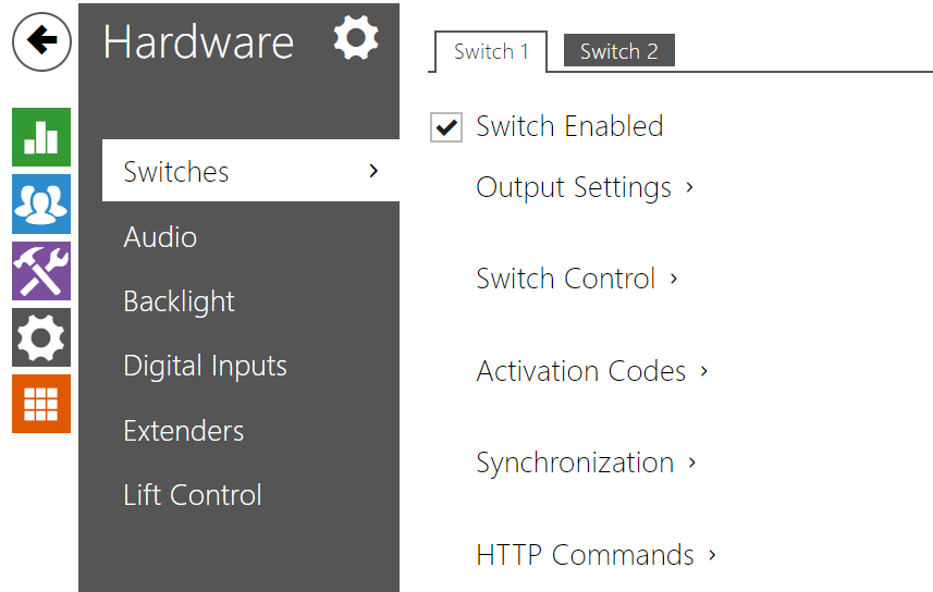
Switch 1–2
 |
- Switch enabled – enable/disable the switch globally. When disabled, the switch cannot be activated by any of the available codes (including user switch codes), by a call or quick dial button.
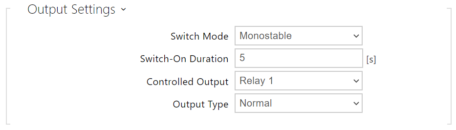 |
- Switch mode – set the monostable/bistable mode for the switch. The switch is switched off after a timeout in the monostable mode and switched on with the first activation and off with the next activation in the bistable mode.
- Switch-on duration – set the switch-on time for a monostable switch. This value is not applied in the bistable mode.
- Controlled Output – assign a physical output to the switch. Choose one of the available device outputs: relay, active output, extender output. If you select None, the switch will not control any physical output but can control external equipment via HTTP commands.
- Output Type – If you are using a Security Relay, set the output type to Security. In Security mode, the output works in inverse mode, i.e., remains closed and controls the Security Relay module using a specific pulse sequence. If you use the Inverse mode (i.e. the door is locked when voltage is applied), set the Inverse output type. In case multiple switches are set to the same output but different output types, the following priority will be applied: 1. Security, 2. Inverse, 3. Normal.
Info
- A switch activation value higher than 1 s can be set for the security output type. A value equal to or higher than 0.1 s can be set for the normal and inverse output types.
Security
- The 12V output is used for lock connection. If, however, the unit (2N IP Intercoms, 2N access control units) is installed where unauthorized tampering may happen, we strongly recommend that the 2N Security Relay (Part No. 9159010) be used for enhanced installation security.
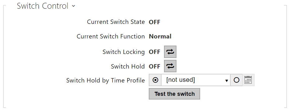 |
- Current Switch State – display the current switch state (On/Off).
- Current Switch Function – Display the current switch function.
- Normal: the switch is not locked or held.
- Held: the switch is held and unlocked.
- Locked: the switch is locked (locking has priority over holding, the holding state is irrelevant in this case).
- Switch Locking – toggle between the unlocked and locked states. When the switch is locked (ON), its logical state is 0, and it cannot be controlled until unlocked.
- Switch Hold – on: the switch is permanently in position 1 and cannot be controlled until released (if the switch hold and lock are active at the same time, the switch is locked).Off: the switch not held in position 1.
- Switch Hold by Time Profile – assign a predefined time profile to the switch or set a time profile manually that allows for switch activation. If the assigned time profile is inactive, the switch can be activated by tapping a valid RFID card or entering a code.
- Test the Switch – activate the switch manually to test its function, e.g. an electric lock or another device connected.
Caution
- In case the switch is locked and the device is turned off and on, the switch will be locked after the device is turned on again. The same is true when the switch is disabled and enabled again.
- In case the switch is held and the device is turned off and on, the switch will not be held after the device is turned on again. The switch is held after power on only if a switch hold time profile is set and active at the moment of the power on. The same is true when the switch is disabled and enabled again.
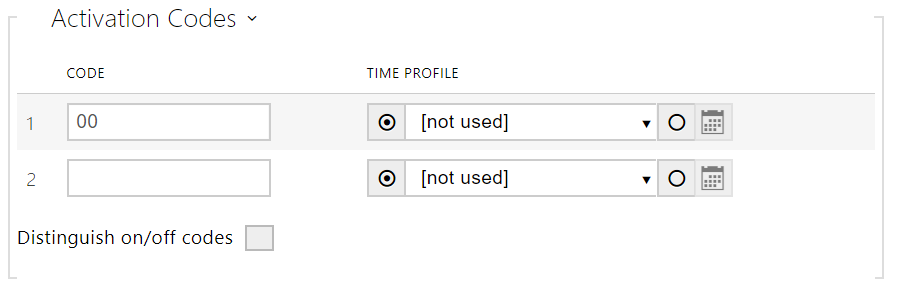 |
- Code – enter the numerical code for the switch. The code must include at least two door unlocking characters via the device keypad and at least one door unlocking character via DTMF. We recommend you to use four characters at least. Codes 00 and 11 cannot be entered and are not accepted from a numeric keypad; they are reserved for opening doors via DTMF. Confirm the code with *. The code length is up to 16 characters.
- Time Profile – assign a time profile to the switch code to control its validity.
- Distinguish on/off codes – set whether codes on odd rows (1, 3, ...) will be used for switch activation, and codes on even rows (2, 4, ...) for deactivation in bistable mode.
 |
- Synchronise With – set switch synchronisation to enable automatic switch activation after another switch activation with a predefined delay. Define the delay in the Synchronisation Delay parameter.
- Synchronisation Delay – set the time interval between synchronised activations of two switches. The parameter will not be applied unless the Synchronise function is enabled.
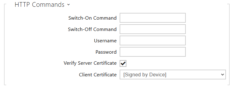 |
- Switch-On Command – set the URL for the HTTP or HTTPS GET request sent on switch activation. The command format is http://ip_address/path. E.g. http://192.168.1.50/relay1=on.
- Switch-Off Command – set the URL for the HTTP or HTTPS GET request sent on switch deactivation. The command format is http://ip_address/path. E.g. http://192.168.1.50/relay1=on.
- Username – set the username for the HTTP commands sent on switch activation and deactivation. Required only if authentication is required.
- Password – set the password for the HTTP commands sent on switch activation and deactivation. Required only if authentication is required.
- Verify Server Certificate – enable this to verify the server public certificate against the CA certificates uploaded to the device.
- Client Certificate – specify the client certificate and private key to be used for server certificate verification.
Tip
In case of use external relay part no.: 9137410E are used next HTTP commands:
To turn on the switch – http://ip_address/state.xml?relayState=1 (e.g.: http://192.168.1.10/state.xml?relayState=1)
To turn on for pre-defined time (default value is 1.5 s) – http://ip_address/state.xml?relayState=2 (e.g.: http://192.168.1.10/state.xml?relayState=2)
To turn off – http://ip_address/state.xml?relayState=0 (e.g.: http://192.168.1.10/state.xml?relayState=0)
In case of use external relay part no.: 9137411E are used next HTTP commands (Symbol X should be replaced with a number of the desired switch):
To turn on the switch – http://ip_address/state.xml?relayXState=1 (e.g.: http://192.168.1.10/state.xml?relay1State=1)
To turn on for pre-defined time (default value is 1.5 s) – http://ip_address/state.xml?relayXState=2 (e.g.: http://192.168.1.10/state.xml?relay1State=2)
To turn off – http://ip_address/state.xml?relayXState=0 (e.g.: http://192.168.1.10/state.xml?relay1State=0)
Advanced
 |
- Output 1 Maximum Power – set the maximum output 1 power value.