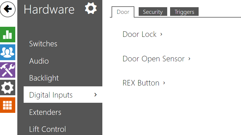
5.3.7 Digital Inputs
In this configuration section set the parameters associated with the digital inputs and their interconnections with other functions.
 |
Door
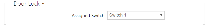 |
- Assigned Switch – select a switch for door lock control. The switch state controls the door unlocking signaling (green door symbol, green LED).
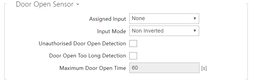 |
- Assigned Input – define one (or none) of the logic inputs for open door detection.
- Unauthorized Door Open Detection – detect that the door has been opened without the assigned door switch being activated first.
- Door Open Too Long Detection – door open too long detection.
- Maximum Door Open Time – duration for which the door can remain open before the Door Open Too Long event is triggered.
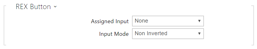 |
- Assigned Input – select a logical input for the exit button function. Activation of the exit button input activates the assigned door lock switch, the switch-on duration and mode of which are configured in the settings of the selected switch.
- Input Mode – set the active input mode (polarity).
Security
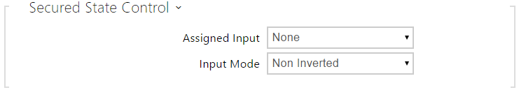 |
- Assigned input – define one (or none) of the logic inputs for secured state detection. The secured state is then signalled by a red LED on the device.
- Input mode – set the active level of the input (polarity).
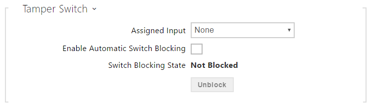 |
The tamper switch equipped models help detect opening of the device cover and signal this event as TamperSwitchActivated. The events are written into a log and read out via HTTP API (refer to the HTTP API manual).
If the function is enabled, all the switches get blocked for 30 minutes whenever the tamper is activated. Blocking is active even after the device restart. Each port can be controlled via Automation. Press the UNBLOCK button, disable the function or reset the configuration factory values to unblock the switches.
- Assigned input – select the logic input to which the tamper switch is to be connected. TamperSwitchActivated signals the tamper switch activation.
- Automatic switch blocking – block the switches by tamper activation for 30 minutes.
- Switch blocking state – display and make switch blocking settings.
Note
Applies to the 2N Access Unit model:
- From PCB version 599v2 up, all devices are equipped with an optical tamper switch.
- From PCB version 599v2 up, the assigned input is indicated by a module pictogram backlight. In lower PCB versions, it is indicated by the LED light on the right-hand module side.
Triggers
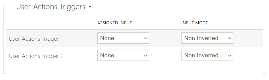 |
- User Actions Trigger 1, 2
- Assigned input – select a logic input that will fulfil the user action function. In case the function is activated, the UserActionActivated event with parameter state=in (function deactivation is indicated by state=out) is written into the device event log. Based on this event, for example, superior systems can trigger alarm, lock the whole building or perform any other action.
- Input mode – select whether a user action should be evaluated based on the inverted or normal value of the assigned input.