2N Security Relay - what it is and how to use it with 2N IP Intercom?
The 2N Security Relay is designed for any 2N IP Intercom model with firmware versions 1.15 and higher. It significantly enhances the security of the connected electric lock because it prevents the lock from opening by forced intercom tampering.
Function:
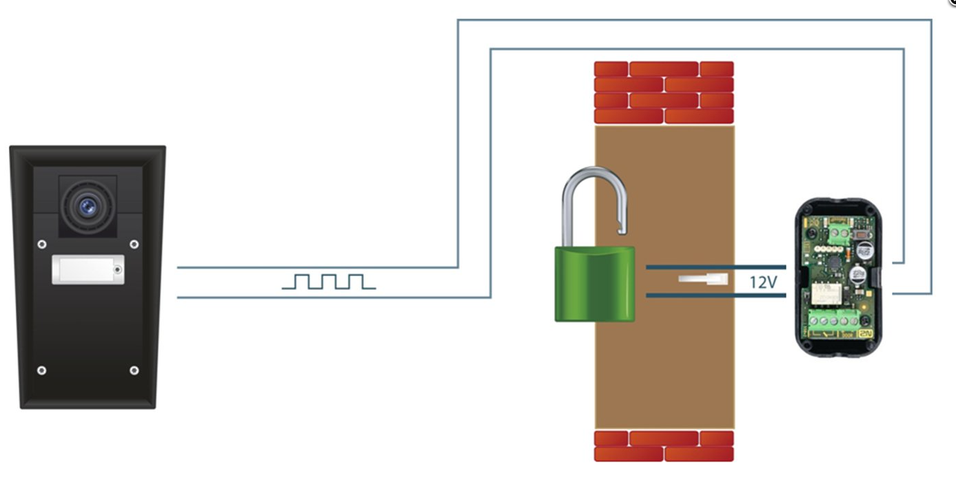
The 2N Security Relay is a small device installed between 2N IP Intercom which is placed outside the secured area and the electric lock installed inside the secured area. The interconnection scheme is shown in the picture below:
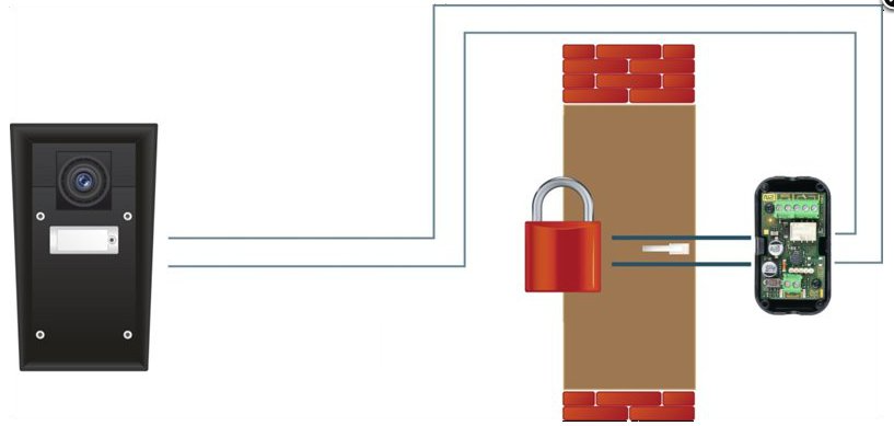
The 2N Security Relay includes a relay that can only be activated if the valid opening code is received from the intercom.
Specifications:
- Passive switch: NO and NC contacts, up to 30V/1A AC/DC
- Active switch output: typically 8 – 13 V DC depending on the power supply (adapter: input voltage minus 0.6V), max 700mA
- Dimensions: 56x31x24mm
- Weight: 20g
Installation:
Install the 2N Security Relay onto a two-wire cable between the intercom and the electric lock inside the area in order to be secured (typically behind the door). The device is powered and controlled via this two-wire cable and so it can be added to an existing installation. Thanks to its compact dimensions the device can be installed into a standard mounting box.
Make sure that the 2N Security Relay is always connected to the intercom's 12V output. The motherboard relay is used for switching lights or other peripherals that do not have to be secured.
Settings for the 2N® IP Vario:
The settings are the same as described below, but in addition, you need to change the jumpers on the configuration connector on the PCB to position normally OPEN and Lock Power Supply settings can be set either external or internal. Then, after setting of the Security mode, the relay is powered and works correctly. These jumper settings are described in the 2.3 Electric Installation.
Connection:
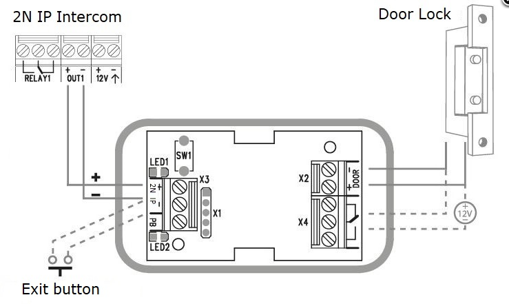
Note: Keep in mind the polarity (see the picture below)
Connect the 2N Security Relay to the intercom as follows:
- To the intercom active output (OUT1 or OUT2)
Connect the electric lock to the 2N Security Relay output as follows:
- To the active 12V/700mA DC output, or
- To the relay output with a serial external power supply.
The device also supports a Departure button (you can use our own 2N Exit button – order number is 9159013) connected between the "PB" and "2N IP" terminals. When you press the departure button, you will activate the output for 5 seconds.
 Status signalling:
There are two LED diodes placed in the 2N Security Relay. In the table below you can find what does it mean if these diodes blink, shine or are off.
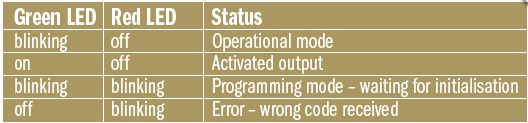
Note: "Green LED" from the table corresponds to "LED1" in the picture above. "Red LED" corresponds to "LED2".
Configuration:
- Connect the 2N Security Relay to the proper switch output – this is described below in the chapter "How to configure 2N IP Intercom". Make sure that one LED at least on the 2N Security Relay is on or blinks.
- Press and hold the 2N Security Relay reset button (SW1 in the picture above) for 5 seconds to put the device in the programming mode (both the red and green LEDs blink).
- Activate the intercom switch by using the keypad, telephone, etc. The first code sent from the intercom will be stored in the memory and considered valid. After code initialization, the 2N IPSecurity Relay will pass into the operational mode (the green LED blinks).
After these steps, you can be sure that nobody will be able to open the door with 12V battery placed between 2N IP Intercom intercom and security relay as shown in the picture below.
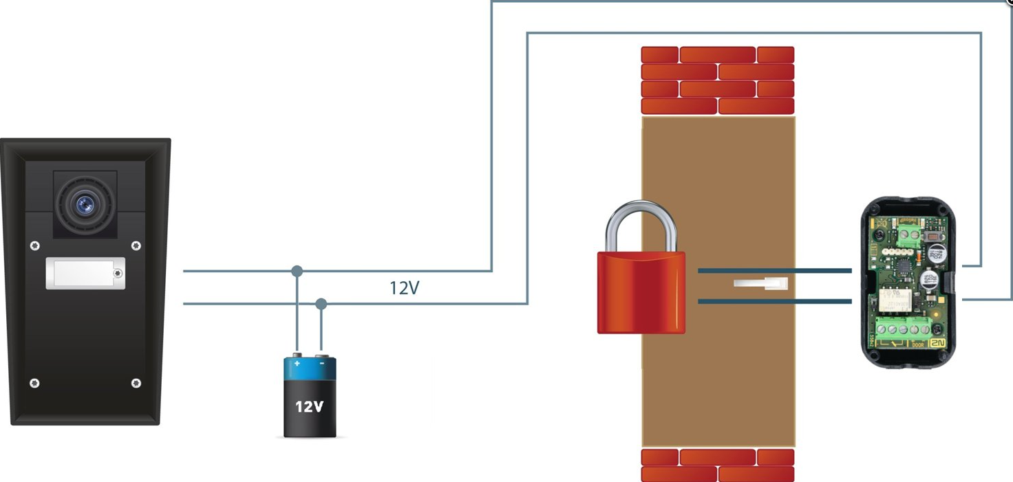
Security relay is programmed in such way that it needs to receive special signal (code for door opening) and only after that it activates the output (active or passive) to which is connected the electrical lock. Without this specific signal, you will never open the door.
How to configure 2N IP Intercom
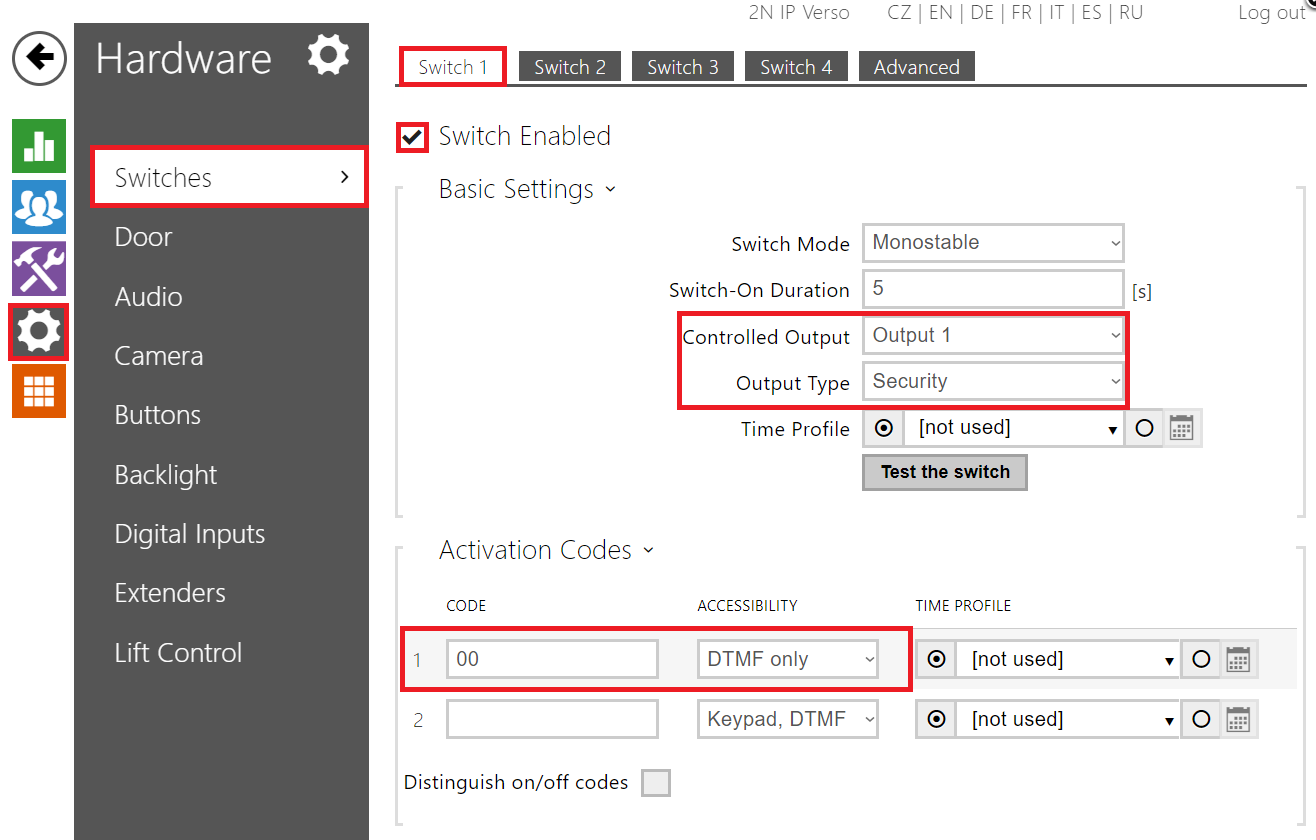
Configuration of 2N IP Intercom intercom is similar as described above. Go to section "Hardware – Switches – Switch 1" and verify that this switch is enabled. Then you have to choose appropriate "Controlled Output" to which is 2N Security Relay connected and set "Output type" to "Security" mode. Finally, specify codes that will activate the switch as is shown in the picture below.
More product information: